|
While I was at MicroCHIPS from 2001 to 2005, I worked on a technology for the controlled exposure of reservoir contents. The exposure mechanism, a hermetic metal seal that is ruptured like an electrical fuse, was invented by my colleagues Scott Uhland and Ben Polito. I spent several years exploring the fabrication and operational possibilities and published a paper with them (Electrothermally activated microchips for implantable drug delivery and biosensing) in the Journal of Controlled Release in 2005.
For my MEng thesis at MIT, I decided to explore possible applications for this technology other than implantable drug delivery, which had been the original focus at MicroCHIPS.
The application of a new technology requires not only a familiarity with the technologys capabilities and limitations, but also an objective study of the potential markets’ needs, economic value, and existing and future competitors and barriers. The process entails a sort of mental juggling in which possible technical embodiments are compared to various markets, costs, and customers. The ideal outcome is a match between an embodiment that requires a minimum of additional development and an application that offers a maximum amount of revenue.
The first alternate application I examined was in vivo glucose sensing, which MicroCHIPS is also investigating. The following is adapted from my thesis notes.
Introduction
Consider a smart packagean automated container that can open itself. It can store its contents indefinitely in a hermetically sealed environment:
Figure 1. Schematic of a controlled-exposure device [Maloney 2005].
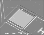
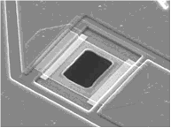
It has no moving parts, no mechanical linkages that might leak or clog. It is opened with a voltage pulse, which resistively heats and ruptures a metal membrane at one end of the container:
|
(a)
|
(b)
|
Figure 2. Micrographs of metal membranes (a) before and (b) after electrothermal
rupture [Maloney 2005].
Multiple containers can be constructed in a batch process, and thousands can be fabricated in parallel on a single substrate. They can be made from biocompatible and biostable materials for use an implantable medical device. In fact, they could be constructed from many possible materials depending on the constraints of the particular application. The only true material requirements are that the substrate and membrane be hermetic and that the membrane conducts electricity.
The containers might be opened one by one, or all at once, or in any combination. They might be filled with any combination of circuits, drugs, sensors, and cells. When opened, they permit, fundamentally, flux: fluids, particles, light, sound, information.
This paper examines a technology for controlled exposure. The concept, only several years old, has not yet been commercialized. In the following sections are described the background of the idea, aspects of the technology, and the conception and details of one possible application.
Background
The hermetic controlled-exposure concept originated in the early 1990s, when Cima and Langer conceived of a silicon microchip that could deliver drugs in vivo [Kirsner 2004]. The first version, shown in Figure 3, contained an array of reservoirs etched in silicon. The reservoirs were capped with gold membranes that could be electrochemically dissolved in saline with an applied voltage [Santini 1999a]. At approximately 1 V, the formation of gold chloride in saline becomes thermodynamically favorable, causing the membrane to dissolve atom by atom (Figure 4).
Figure 3. Schematic of controlled-release microchip configured for the electrochemical exposure mechanism [Santini 1999b].
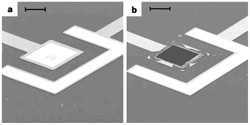
Figure 4. Micrographs of gold membranes (a) before and (b) after electrochemical dissolution. The scale bar is 50 μm. [Santini 1999b].
These devices were used to demonstrate the storage and controlled release of multiple compounds [Santini 1999b]. In 1999, Santini formed MicroCHIPS, Inc. (Bedford, MA) to commercialize this electrochemical mechanism for drug delivery applications. Cima’s and Langer’s groups at MIT have continued to develop and demonstrate similar devices [Li 2004, Shawgo 2004, Voskerician 2004].
 An alternate controlled-exposure mechanism was later invented at MicroCHIPS by Uhland and Polito [Uhland 2004]. This mechanism employs an electrothermal rather than electrochemical process to rupture the metal membrane [Maloney 2005]. Resistive heating from an applied current ruptures the membrane in a process similar to blowing a fuse. The concept is shown in Figure 1 and at right [Webb 2004], and micrographs of membranes before and after electrothermal rupture are shown in Figure 2. An alternate controlled-exposure mechanism was later invented at MicroCHIPS by Uhland and Polito [Uhland 2004]. This mechanism employs an electrothermal rather than electrochemical process to rupture the metal membrane [Maloney 2005]. Resistive heating from an applied current ruptures the membrane in a process similar to blowing a fuse. The concept is shown in Figure 1 and at right [Webb 2004], and micrographs of membranes before and after electrothermal rupture are shown in Figure 2.
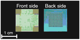
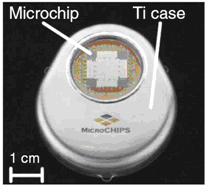
The electrothermal mechanism soon supplanted the electrochemical mechanism at MicroCHIPS for several reasons including faster operation, independence of the membrane material and surrounding environment, and robustness. Microchips with Pt/Ti/Pt membranes were demonstrated in a six-month drug delivery study in which discrete doses of a peptide drug were delivered in beagle dogs [Prescott 2006]. The fully implantable systems used in this study each contained a 100-reservoir microchip, a microprocessor, a battery, and communications telemetry:
|
(a)
|
(b)
|
Figure 5. (a) Representative 100-reservoir drug delivery microchips configured for the electrothermal mechanism. (b) Fully implantable drug delivery device used to demonstrate peptide release over six months in an animal model [Prescott 2006].
Drug and fragrance delivery by the electrochemical mechanism was the focus of a previous thesis [Pakalapati 2003], and is not discussed here. Instead, the thought process for conceiving alternative applications and its conclusions are described. The electrothermal controlled-exposure mechanism might be applied to applications other than implantable drug delivery. The technology, economics, and competitive environment of one particular application, in vivo glucose sensing, are outlined.
Description of the technology
 Microchips are fabricated by depositing a thin dielectric layer on a substrate, depositing and patterning metal circuitry and membranes on one side, creating a cavity by etching from the back side, and removing the dielectric layer underneath the membrane [Maloney 2005]. In one embodiment, the dielectric layer is low-pressure chemical-vapor-deposited (LPCVD) silicon nitride. A single metal such as sputtered gold comprises the circuitry and membranes, and the cavities are etched by aqueous potassium hydroxide. In another embodiment, the dielectric layer is thermally grown silicon dioxide, and the cavities are etched by deep reactive ion etching (DRIE). Microchips are fabricated by depositing a thin dielectric layer on a substrate, depositing and patterning metal circuitry and membranes on one side, creating a cavity by etching from the back side, and removing the dielectric layer underneath the membrane [Maloney 2005]. In one embodiment, the dielectric layer is low-pressure chemical-vapor-deposited (LPCVD) silicon nitride. A single metal such as sputtered gold comprises the circuitry and membranes, and the cavities are etched by aqueous potassium hydroxide. In another embodiment, the dielectric layer is thermally grown silicon dioxide, and the cavities are etched by deep reactive ion etching (DRIE).
In still another embodiment, two different materials are used for the circuitry and the membranes to decouple their functions and increase efficiency. For example, it is most desirable for the circuit metal to have a low electrical resistivity since the heat generated in the traces does no useful work. In contrast, it is most desirable for the membrane metal to have a higher resistivity to generate resistive heat to rupture the membrane. Both materials should be amenable to thin film deposition and patterning, and both should be resistant to the environment in which the device is placed. For example, the microchips used in the six-month animal study contained gold traces and Pt/Ti/Pt membranes [Prescott 2006].The membrane material was predominantly titanium because of its high electrical resistivity and biocompatibility. Thin layers of platinum were deposited before and after the titanium to provide an inert coating on each side of the membrane.
The mechanism has been tested in air and water by applying different currents. Shown in Figure 6 is the relationship between applied current and resulting opening area, as measured by a calibrated optical microscope and imaging software. The relationship is monotonic for currents larger than 0.5 A, and the preferred regime of activation is at approximately 1 A, where activation is reliable and repeatable. Micrographs of representative membranes before and after activation are shown in Figure 2, in which the exposed area after activation is approximately 50x50 μm².
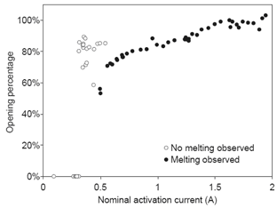
Figure 6. Opening area as a function of activation current for a Pt/Ti/Pt membrane immersed in water [Maloney 2005].
An often-heard question about the electrothermal technology concerns the amount of heat dissipated near the membrane. If the temperature is high enough to melt titanium and platinum, wouldnt the reservoir contents be degraded? A simple calculation shows that the energy dissipated is not sufficient to damage any meaningful amount of material [Maloney 2005]. Devices typically require 5 V and 1 A for activation, and the activation process is complete in approximately 10 μs. Only a few tens of microjoules of energy is therefore dissipated near the membrane, not enough to heat even a few micrograms of solid material by a temperature increase of 10°C.
What are the interesting aspects of this technology? First, the mechanism is hermetic. Other groups have explored the controlled-exposure aspect with polymers. For example, Low investigated voltage-controlled hydrogel valves to control fluid flow through etched openings in a silicon substrate [Low 2000]. Jager proposed a “cell clinic” in which single cells are confined in wells capped with polypyrrole actuator lids [Jager 2002]. Grayson demonstrated a drug delivery device that releases its contents through the passive degradation of polymer lids [Grayson 2003]. None of these devices are vapor tight. The metal membranes are hermetic to 10-9 atm-cc/s, corresponding to an ability to exclude water vapor over a time span of years [Santini 2006]. Second, the mechanism can be produced in a batch process. Thousands of cavities and membrane caps can be fabricated in parallel on a single substrate by conventional micromachining techniques. Third, the mechanism can operate in nearly any environment and can be activated instantaneously. These abilities differentiate the electrothermal process from the original electrochemical process, which requires immersion in an electrolyte and takes many minutes to achieve complete exposure [Li 2004].
There are multiple ways to position any new technology in the marketplace. The electrothermal mechanism can be thought of as a “smart package” [Santini 2006]. This view represents a shift from the microchip-as-complete-implant concept that was prevalent during early development and the formation of MicroCHIPS. It also leads naturally to a business model that involves partnering with a company that provides the contents to be exposed.
Finding an application
Several questions are useful in identifying an appropriate application or market for a new technology. First, what are the capabilities and limitations of the new technology? Although it is more common to compare concepts by their respective strengths, it is illuminating to also explore the constraints and eliminate applications where the constraints are the limiting factor. For example, the relatively small payload of Santini's controlled release microchips led MicroCHIPS to investigate the in vivo release of only the most potent compounds [Santini 1999a]. Second, in what applications is the technology necessary? Countless interesting ideas have failed in the marketplace because they did not provide a sufficient advance to justify their expense. Third, are the markets lucrative? Alternatively, is the market prominent? The application of any new technology desirably leads to a large revenue stream. However, a prominent application involving a long-sought-after goal could also be favorable if it attracts public attention and more investors. Fourth, how would value be extracted? Fifth, what is the competition? Competition can take the form of existing companies, insurmountable IP barriers, or future developments that could supersede the technology.
The first question, involving advantages and limitations, can be answered immediately. We can then address the remaining questions for a single application that is thought to be particularly favorable.
Capabilities and limitations
The technology has the following general capabilities and characteristics [Santini 1999a, Maloney 2005]:
Hermetic long-term storage of material in solid, liquid, or gel form.
Large arrays of discrete cavities containing a variety of contents.
Exposure on command of drugs, sensors, cells, or other contents, or a combination of these.
Automated, closed-loop system regulation.
However, a number of limitations are apparent:
Cavity contents cannot be changed after the sealing process, and the device cannot be reused after the membranes are ruptured. Exposure is thus limited to one-time use only; the device is not a hermetic valve.
Membranes are individually addressed, making the device difficult to access electrically when large arrays of cavities are fabricated.
The instantaneous current requirement of 1 A is challenging to supply in some applications such as medical implantation. The power requirements are strongly coupled to the membrane material, which may be constrained by strength, hermeticity, and biostability requirements.
The <1 μL payload limits the number of possible dispensing applications. The payload could be increased by increasing the substrate thickness at the cost of increasing the required diffusion length, characteristic release time, and device size.
The technology at this point costs more than mature dispensing methods such as microsyringes.
The food and drug administration (FDA) has not (yet) approved this technology for use.
The drug delivery application was discussed in a previous MEng thesis [Pakalapati 2003]. There are enough other possibilities, even with the limitations given above, to move beyond drug delivery and consider controlled exposure of other materials or flows: sensors, cells, fluids, RF, or light. One possible application is the sequential exposure of multiple short-term sensors in vivo, and this is the application selected for analysis in this paper. Another is the exposure of pathogen sensors in the battlefield. A disposable chip could expose finite surface areas to the analyte in a sequential manner, until all of the sense spots on the arrayed chip are used up. Another is the exposure of many different sensors to a sample stream for large-array diagnostic screening in the lab.
Selected application: in vivo glucose sensing
There are several appealing aspects to the glucose sensor application. First, the mechanism can be integrated in its current form with little additional development. Second, the mechanism allows a significant improvement in the state of the art. Third, the market is large. Tens of millions of Americans have diabetes, and approximately one million more are diagnosed each year. A percentage of these patients require frequent glucose sensing to guide insulin delivery, and the market for glucose sensing is in the billions of dollars [Sandred 2004]. The following sections describe the detail behind these assessments.
Necessity of the technology
What advances would the technology enable in the marketplace? To answer this question, it is necessary to outline the diabetes problem and describe current glucose sensor technology.
Diabetes is a metabolic disorder, an inability to maintain a normal blood glucose level [NDIC 2006]. Patients with diabetes have a problem producing insulin, a hormone normally secreted by the pancreas. Insulin mediates the transfer of glucose from the bloodstream to cells, and a deficiency of insulin results in an increase in blood glucose levels (hyperglycemia) that is physiologically harmful. The problem is managed by monitoring blood glucose levels and self-administering insulin when needed.
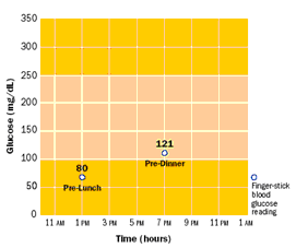
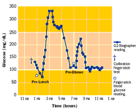
Blood glucose is most commonly checked by finger stickingpuncturing the skin to produce a small amount of blood, which is applied to a diagnostic strip. A normal level is approximately 80-120 mg/dl; higher levels are handled by injecting insulin through a syringe or pump. However, occasional finger stick checks can easily miss excursions outside normal glucose levels, as illustrated in Figure 7. A ten-year clinical study of 1,441 volunteers showed that “keeping blood glucose levels as close to normal as possible slows the onset and progression of eye, kidney, and nerve diseases caused by diabetes” [NDIC 2006]. Blood glucose testing four or more times a day was an essential part of the recommended management protocol.
|
(a)
|
(b)
|
Figure 7. Comparison of (a) occasional and (b) continuous glucose measurement [Glucowatch 2006].
The health advantages identified by this study and others have prompted research into continuous sensing. Aside from a cure, the best way of managing diabetes would be what has been termed an “artificial pancreas”a closed-loop system that would monitor blood glucose and deliver insulin whenever needed by a fully implantable or transcutaneous insulin pump. However, development of such a system has been difficult, in part due to the limitations of implantable glucose sensors.
The most common type of implantable glucose sensor relies on an enzyme-based amperometric mechanism [Ward 2002]. Glucose oxidase, an enzyme, oxidizes the glucose molecule to form hydrogen peroxide and gluconic acid. The hydrogen peroxide is then oxidized by an electrode at 0.7 V to form oxygen and water. The oxidization process at the electrode produces a current that, in theory, corresponds to the blood glucose concentration. This sensor can also be used subcutaneously, as the concentration of glucose in interstitial fluid tracks with the concentration in blood with a time delay of several minutes.
A limitation to this design is that the voltage used to oxidize hydrogen peroxide also oxidizes other molecules. For example, acetaminophen and ascorbate (vitamin C) are also electroactive at 0.7 V [Palleschi 1986]. A semipermeable membrane is therefore added over the electrode that favors the diffusion of the smaller hydrogen peroxide molecule. A suitable membrane material is a composite of cellulose acetate and Nafion, a sulfonated copolymer [Zhang 1994].
A second limitation is that the relatively low oxygen levels in physiological fluid threaten to make the enzyme-catalyzed reaction oxygen-limited instead of glucose-limited. An additional surrounding semipermeable membrane is necessary to promote oxygen diffusion over glucose diffusion [Ward 2002]. This membrane adds an additional time delay but is necessary to ensure that the oxidation current is proportional only to glucose concentration. An illustration of a sensor design with both inner and outer membranes is shown in Figure 8.
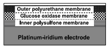
Figure 8. Schematic of enzyme-based amperometric glucose sensor [Ward 2002].
A third limitation is that the enzyme membrane is susceptible to fouling from macrophages, proteins, and protein fragments [Wisniewski 2001]. The oxygen-permeable outer membrane therefore handles an additional duty, that of protecting the enzyme from in vivo attack. Even with a barrier layer, however, the enzyme degrades over time [Valdes 2000]. The typical usable lifetime is several weeks, and this duration has an important effect on device use [Heller 1999]. Because the sensor lifetime is too short for full surgical implantation and removal to be practical, the sensor must be inserted transcutaneously with an electrical connection to an external monitor. The FDA limits transcutaneous insertion to 72 hours because of the risk of infection. Consequently, each sensor can only be used for three days before it must be discarded [Sheppard 2006].
The electrothermal mechanism could be integrated with this glucose sensor [Santini 2003]. The combination of these technologies would enable a long-term device consisting of multiple short-term sensors. After the enzyme on each sensor degrades beyond usefulness, an additional sensor would be exposed by microprocessor control. One way of combining the devices would be to fabricate the sensor and deposit the enzyme and polymer membranes as is done now, then attach a controlled-release cap by a suitable low-temperature hermetic sealing process [Uhland 2005]. The envisioned fully implantable device would contain sensors packaged in controlled-exposure cavities, a microprocessor, a telemetry antenna, and a battery, all contained within a titanium housing. With a sufficient number of hermetically sealed sensors, the implanted device could operate for years before surgical removal and replacement.
Market value, business model, and value extraction
What is the market for a multi-year, implantable, continuous glucose sensor? It is helpful to identify the expected customer population and the current costs of glucose measurement. These figures offer perspective for evaluating whether the cost of the fully implantable device is reasonable.
It is clear that a reliable continuous glucose sensor has long been desired by patients. Their anticipations and concerns are expressed in dozens of online weblogs [DiabetesMonitor 2006]:
“Continuous monitor lust. They're starting to hit the market en force, but still aren't quite affordable or practical... And now MiniMed's new first-ever combo pump/continuous monitor system (Paradigm REAL-Time) looks pretty darn exciting, but still runs high ($1,000 on top of pump price, plus ?? sensor costs), and is still not covered by insurance. In short, waiting IMPATIENTLY for new technology to come to my aid here. Old story, new (im)patient.” [DiabetesMine 2006].
“OK here's the bad news [on augmenting an insulin pump with a 3-day continuous glucose sensor]: The total cost of the upgrade is $1100.00. Yeah, ouch... I have it on good authority that insurance companies (mine included, and I checked months ago) are covering the cost of the sensor purchase. Sweet. They are not, however, covering the cost of the Transmitter itself, even with a new pump purchase. Sour... I've got some serious raging hormones on for this sucker. No more human pincushion. No more testing twelve times a day, sometimes 15. Sometimes 20. And still managing to miss trends, knowing there's something there that I'm sure I'm JUST NOT GETTING. No more waking up five times during the damn night once a month just to make sure I'm not missing something, like a Hypo. Quicker reaction time. BG results Every Five Minutes.” [CandidDiabetes 2006].
“The system in [Medtronics combination insulin pump and 3-day continuous glucose sensor] Paradigm apparently reads the blood every ten seconds and gives an average reading every five minutes. I called MiniMed the second I found out the technology was approved. I asked what costs were associated with it. They told me the technology was already built in to the pump. They said any new pump ordered would be activated and the sensors are $40 each, which need to be replaced every three days. Read: $400 per month. Then, finally, the woman on the phone told me the transmitter from the sensor to the pump has a one-time set-up fee of $999. Ahhhhh!!!! I wish people could just be upfront about these things. I think a thousand dollar fee doesn't quite fall into the category of hidden. But, the Cozmo doesn't seem to be anywhere close to this technology and the Dexcom has a ten-minute delay and is a hefty piece of equipment. Unfortunately, MiniMed wins.” [DiabeticWonder 2006].
(From an early user of the Medtronic Guardian 3-day continuous glucose monitor) “Today I didn't have to worry about my blood sugar. The Guardian is worrying about it for me. If it goes too high shell tell me. If it goes too low she'll tell me. So today I could focus my mind on my work, not on my diabetes. What a gift! ... So do I like it? Absolutely. Is it worth what it has cost me? Double absolutely. Would I do it again? Triple absolutely.” [Dubois 2005].
The number of expected buyers is smaller than the total diabetes population, since not all patients are frequent testers. Spurgeon et al suggest that the expected early adopters of continuous glucose sensing devices are insulin pump users (200,000 in U.S.), patients with “brittle” or unstable diabetes (number unknown), patients unable to detect hypoglycemia (number unknown), children with diabetes (200,000), pregnant women (140,000-150,000), and technocrats (number unknown) [Spurgeon 2005].
A caveat when estimating the number of potential customers is that the fully implantable device would require a more invasive insertion procedure than the current transcutaneous needles. The needles are currently patient-inserted, while the long-term device would be implanted surgically. Still, the subcutaneous implantation procedure could be done on an outpatient basis and would only be required between once and several times every ten years. The quotes above indicate that the benefits of reduced finger stick testing (to a calibration frequency only) and continuous glucose data could convince many patients to undergo the procedure.
The cost of strips and meters for frequent testers is approximately $5,000 per year [Canadian Diabetes Association 2003, Mendosa 2006]. These expenses represent a majority of the total market for self-monitoring of blood glucose, estimated to be $5 billion per year [Sandred 2004].
Particularly evident in the comments above is the potential buyers’ concern about cost. Both patients and device companies have a strong interest in insurance company reimbursement. Reimbursement is judged to be cost effective if the health advantages (quantified as “quality-adjusted life years”) outweigh the management costs. For example, the New England Health Institute calculated that the ratio of cost to benefit for continuous glucose sensing was approximately $51,000 per quality-adjusted life year [Spurgeon 2005]. Amounts less than $100,000 per quality-adjusted life year are generally thought to be favorable in the U.S. [Spurgeon 2005]. This study estimated that the continuous sensor would cost twice the amount of strips, or approximately $10,000 per year.
The use of twice the cost of strips is, coincidentally or not, a good estimate of the cost of the envisioned controlled-exposure device. Most of the components (medical device battery, titanium housing, microprocessor, and telemetry) are identical to those used in pacemakers, which cost approximately $10,000 [Tsao 2003, Robotham 2004]. Each enzyme-based glucose sensor, packaged independently, costs $35. The microchip cost is also small compared to the cost of the other implant components (the exact cost is proprietary). A total implant price to customers of approximately $10,000 is therefore estimated, and this implies a revenue on the order of $1B for every round of implants purchased by a patient population of 100,000. A tradeoff appears between designing an implant that operates longer in vivo (better patient satisfaction) and a shorter-term implant (more frequent purchase).
The current Blue Cross policy is to reimburse expenses for cases in which frequent glucose testing is medically necessary:
Use of invasive subcutaneous or noninvasive continuous interstitial glucose monitoring devices (i.e., Minimed Continuous Glucose Monitoring System [CGMS] or the GlucoWatch Biographer) adjunct to standard care are considered medically necessary in the care of patients with Type 1 diabetes, when all of the following criteria are met:
- Inadequate glycemic control despite compliance with frequent self-monitoring (at least four times per day) and including fasting hyperglycemia (>150 mg/dl) or recurring episodes of severe hypoglycemia (<50 mg/dl). This poor control is in spite of compliance with multiple alterations in self-monitoring and insulin administration regimens to optimize care; and
- Insulin injections are required 3 or more times per day or an insulin pump is used for maintenance of blood sugar control; and
- Four or more fingersticks are required per day
[Blue Cross 2006]
These criteria correspond to most of the patient population described above, with the exception of the technocrats (who may be willing to purchase the device out-of-pocket). As a reference, Medicare approved reimbursement of Medtronic Minimeds 3-day transcutaneous sensor four years after the FDA approved it for use and presumably after the device had been clearly demonstrated to be useful [Minimed 2006].
The envisioned business model is to partner with a medical device company that already has an implantable glucose sensor and the resources to acquire FDA approval. The device company would manage the FDA approval process with the cooperation of the engineers working on the exposure technology. The device company would also sell the product and pay a negotiated licensing fee based on sales to the inventors of the controlled-exposure device.
Candidates for partnership include any company developing an implantable glucose sensor. Suitable devices include Abbotts Freestyle Navigator, Medtronic Minimeds Guardian/Paradigm, and Dexcoms STS. A suitable company would need to have the resources to pursue the project through pre-clinical and clinical tests, the FDA approval process, and the time for acquire customers and insurance reimbursement.
Competition
Alternate glucose measurement methods could represent competition if they are reliable and less invasive. However, no such device has been demonstrated. For example, the Glucowatch Biographer is a wristwatch-like device that operates by reverse iontophoresis [Glucowatch 2006]. However, users report that the device “burns” during operation and frequently stops working, for example during periods of excess perspiration (one user commented, “I put the watch on my outer arm, and I swear it feels like I'm getting burned. I've been able to tolerate it, but it is very uncomfortable.”) [Weaver 2004, Gillis 2006]. The company has acknowledged that skin irritation is a problem and now plans to switch to a microneedle array [Davis 2006]. Other glucose measurement approaches include infrared spectroscopy, thermal radiation, ultrasonic skin poration, glucose-sensitive contact lenses, and tattooable fluorescent beads [Pickup 1999, Davis 2006, Mendosa 2006]. Again, none of these devices has proved as reliable as blood or interstitial fluid testing, and these noninvasive approaches are currently limited to adjunct diagnostics.
It is impossible to guarantee that a noninvasive method of measuring blood glucose will not emerge in the next few years, making an implantable device undesirable in comparison. However, the methods attempted so far have been limited by signal interference and other difficulties in obtaining accurate readings. The (albeit invasive) enzyme-based sensor has been proven in vivo, as has the electrothermal mechanism. There is a therefore clear path to assembling a reliable device that satisfies patients at a cost palatable to healthcare companies.
References
Bassous E et al 1977 Ink jet printing nozzle arrays etched in silicon App Phys Lett 31 135-137
Blue Cross 2006 Medical policy for glucose monitoring and related supplies
Canadian Diabetes Association 2003 Diabetes: an investment for the future health of Canadians
CandidDiabetes 2006
Davis J L 2006 Glucose meters: whats on the horizon?
DiabetesMine 2006
DiabetesMonitor 2006
DiabeticWonder 2006
Dubois W 2005 Life after Dxthe Guardian chronicles
Gillis J 2006 New devices may free diabetics from constant monitoring Washington Post
Glucowatch 2006
Grayson A C R et al 2003 Multi-pulse drug delivery from a resorbable polymeric microchip device Nature Mat 2 767-772
Heller A 1999 Implanted electrochemical glucose sensors for the management of diabetes Annu Rev Biomed Eng 1 153-75
Jager E W H 2002 The cell clinic: closable microvials for single cell studies Biomed Microdevices 4 177-187
Kirsner S 2004 The right dose via microchip Boston Globe
Li Y et al 2004 In vivo release from a drug delivery MEMS device J Controlled Release 100 211-219
Low L-M et al 2000 Microactuators toward microvalves for responsive controlled drug delivery Sensors Actuators 67B 149-160
Maloney J M et al 2005 Electrothermally actuated arrays for drug delivery and biosensing J Controlled Release 109 244-255
Mendosa D 2006 On-line diabetes resources: blood glucose meters
Minimed 2006 Company history
NDIC 2006 Diabetes control and complications trial
Pakalapati L V V 2003 Controlled Release Microchip MEng thesis, Department of Materials Science and Engineering, MIT
Palleschi G et al 1986 A study of interferences in glucose measurements in blood by hydrogen peroxide based glucose probes Anal Biochem 159 114-21
Pickup J et al 1999 In vivo glucose sensing for diabetes management: progress towards non-invasive monitoring British Medical Journal 319 1289
Prescott J H et al 2006 Chronic, programmed polypeptide delivery from an implanted, multireservoir microchip device Nature Biotechnol 24 437-438
Robotham J 2004 Patients march to beat of different pacemaker Sydney Morning Herald
Sandred J 2004 $1 billion medical deal: Abbott Labs to buy Therasense, maker of glucose monitors San Francisco Chronicle
Santini J T 1999a A controlled release microchip PhD thesis, Massachusetts Institute of Technology, Cambridge MA
Santini J T et al 1999b A controlled release microchip Nature 397 335-338
Santini J T et al 2003 Microfabricated devices for the storage and selective exposure of chemicals and devices, US patent 6,551,838
Santini J T 2006 Microchips for implantable drug delivery and biosensing MIT MTL VLSI Lecture Series, March 14, 2006, Cambridge MA
Shawgo R S et al 2004 Repeated in vivo electrochemical activation and the biological effects of microelectromechanical systems drug delivery device J Biomed Mater Res A 71 559-68
Sheppard N F 2006 Personal communication with Norman Sheppard, PhD, MicroCHIPS, Inc., Bedford MA
Spurgeon S A et al 2005 Continuous glucose monitoring: innovation in the management of diabetes New England Healthcare Institute Innovation Series
Tsao A 2003 Medtronic and St. Jude: pumping profits Business Week
Uhland S A et al 2004 Controlled release device and method using electrothermalablation, US patent application 20040121486
Uhland S A et al 2005 Hermetically sealed microchip reservoir devices, US patent application 20050077584
Valdes T I 2000 In vitro and in vivo degradation of glucose oxidase enzyme used for an implantable glucose biosensor Diabetes Tech Therapeut 2 367-376
Voskerician G et al 2004 In vivo inflammatory and wound healing effects of gold electrode voltammetry for MEMS micro-reservoir drug delivery device IEEE Trans Biomed Eng 51 627-35
Ward W K et al 2002 A new amperometric glucose microsensor: in vitro and short-term in vivo evaluation Biosensor Bioelectronics 17 181-189
Weaver K 2004 Living with diabetes
Webb C E 2004 Chip shots IEEE Spectrum (October 2004)
Wisniewski N et al 2001 Decreased analyte transport through implanted membranes: differentiation of biofouling from tissue effects J Biomed Mat Res 57 513-521
Zhang Y et al 1994 Elimination of the acetaminophen interference in an implantable glucose sensor Anal Chem 66 1183-8
|