While working as a MEMS engineer, I occasionally saw peculiar features
on submicron suspended metal films. Cross sections acquired by focused ion beam showed that the films were intact but plastically deformed. Because some of the devices had been implanted in animals,
I first attributed the features to
biological exposure. However, they were later observed after experiments in saline. Some patterns even appeared during the fabrication process. The most likely explanation seemed that they were caused by drying stresses.
are
usually unnoticeable—the walls of a house do not buckle as
paint dries. If a drying fluid contacts a relatively compliant
support, however, the stress may well be enough to cause local or
general buckling of the support.
A clue to the deformation mechanism came from a passage from Porter and Easterling's “Phase Transformations
in Metals and Alloys” and the accompanying illustration:
“Note that the vertical component of γSL remains unbalanced.
Given time this force would pull the mould surface upwards until the
surface tension forces balance in all directions. Therefore Equation
4.14 only gives the optimum embryo shape on the condition that the
mould walls remain planar.”
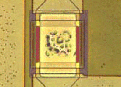
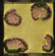
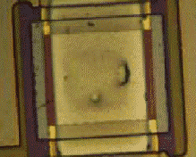
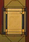
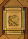
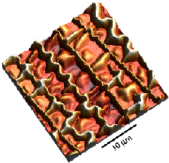
In this case, the substrate, the membrane, wasn't strong enough to
remain planar. Thus, the features (compared below in visual and optical profilometric
micrographs) seem to be caused by the out-of-plane component of the surface tension of drying droplets. Our attempts to reproduce the phenomenon in the lab were only partly successful; experiments with drying fluids led to features, but never those as varied as the examples shown above. We therefore still don’t fully understand the details of the mechanism. Fortunately, the features do not affect the operation of the
films. If necessary, they could be eliminated by engineering
the membrane for higher stiffness or by incorporating a preexisting
tensile stress to offset the buckling.


Since first observing the
features, I've collected other examples of thin film patterns in
the literature. The variety is fantastic, but I haven't found any
that perfectly match the original features. Most buckled films
display very regular, periodic patterns that do not resemble the
blotchy, irregular arrangement of features shown in optical and AFM
micrographs above. The closest patterns are those of drying liquids
as they dewet substrates. The
random arrangement of droplets bears a much stronger resemblance to
the original features than the folded films. It may simply be that
nobody has combined dewetting experiments
with extremely compliant free-standing films before and published the
results. (Until 2007, shortly after I drafted the first version of this note: see From Science to Engineering at the bottom of this page.)
This note summarizes these
findings for the interest of others. Mounds, bumps, wrinkles,
dimples… There are as many descriptions as images. The original
nomenclature of the authors is the best accompaniment.
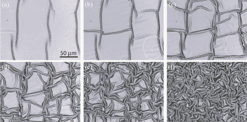
Thin film buckling
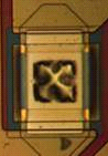
We begin with the compressive buckling of thin
films. Suspended square membranes undergo at least two buckling
transitions. The first is characterized by a domed shape that
continues into an X, or
saltire, under higher stress.
The second resembles an augmented tetraskelion
whose folded features become more prominent with increasing stress or
membrane area. I've often seen these patterns on
ceramic and metal membranes and can usually distinguish them from
the random bumps that seem to be related to drying fluids.
(Ziebert
et al., “Strongly buckled square
micromachined membranes,” J MEMS 8
423-432, 1999)
Back in 1989, Ali Argon at MIT published some photos of SiC deposited on (and subsequently delaminating from) silicon by plasma-assisted (now termed plasma-enhanced) chemical vapor deposition; these look quite similar to the features I characterized:
(Argon et al. “Intrinsic toughness of interfaces between SiC
coatings and substrates of Si or C fibre”
J Materials Science 24 1207-1218 1989)
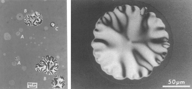
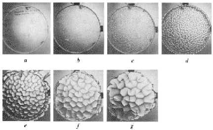
Toyoichi Tanaka, also at MIT, studied gels of
acrylamide and the effect of osmotic
swelling in water. As the outer portion of the gel swells due to a
phase transition, the unaffected interior region transmits a
compressive stress to the surface. Now we start getting into some elegant evocative descriptions:
When a polymer
gel undergoes an extensive swelling, a beautiful, regular pattern
appears on the surface... At the beginning,
the pattern is extremely fine, having a texture similar to that of a
frosted glass. As time goes on, the units of pattern coalesce,
doubling their characteristic size. When
the unit size becomes comparable to the size of the gel, the pattern
gradually disappears.”
Tanaka also describes the patterns as
having “cusps” and “thorns.”
(Tanaka et al. “Mechanical
instability of gels at the phase transition” Nature 325
396-398 1987)
Annie Viallet at
Joseph Fourier University investigated the shapes created in lipid
vesicles during osmotic deswelling of the interior.
When the
reduced volume of partially deflated vesicles varies, a great variety
of shapes (pears, peanuts, starfish…) is observed.”
A great
variety of vesicle shapes were obtained in the chamber at the end of
the shrinkage process: ellipsoids, dumbbells, stomatocytes,
discocytes, pears, stars, etc.”
As in the
case for slow shrinkage, we observed various shapes…the formation
of multiple small invaginations of the membrane pointed toward the
interior of the vesicles, which looked like raspberries…the
formation of lipid pearl necklaces.”
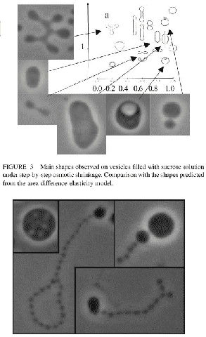
(Viallat
et al. “Giant lipid vesicles filled with a gel: shape
instability induced by osmotic shrinkage” Biophys J 86
2179-2187 2004)
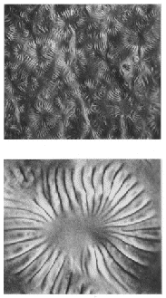
The breaking of axial symmetry in the
glassy skin of drying polysaccharide dextran leads to a pentagonal
arrangement of radial wrinkles:
(Pauchard
et al. “Stable and unstable surface evolution during the drying
of a polymer solution drop” Phys Rev E 68 052801
2003)
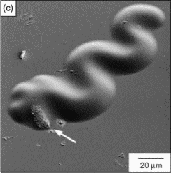
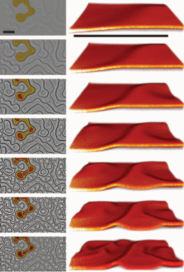
Drying droplets of colloidal polystyrene become buckled and folded (photographs are on top, simulated shapes below):
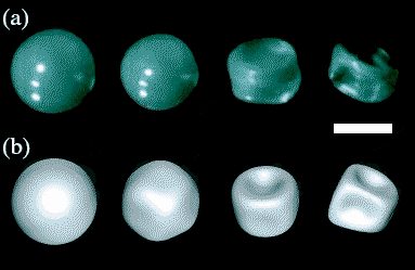
(Tsapis
et al. “Onset of buckling in drying droplets of colloidal
suspensions” Phys Rev Lett 94 018302
2005)
...and “blisters” appear as a polymer film swells in water:
(Sharp et al. “Swelling-induced
morphology in ultrathin supported films of poly(d,l-lactide)”
Phys Rev E 66 011801 2002)
Simulations of tethered membranes produce a “wavelike pattern
of mounds”:
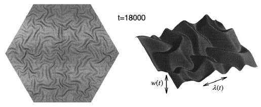
(Moldovan et al. “Tethered
membranes far from equilibrium: buckling dynamics” Phys Rev E
60 4377 1999)
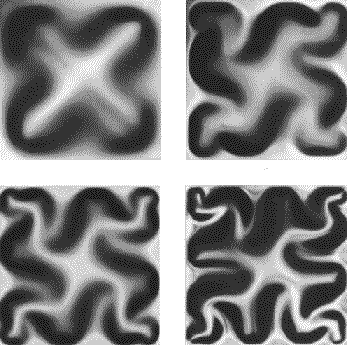
Another group's analysis predicts “ridges,” “cones,”
“mounds,” and “basins”:
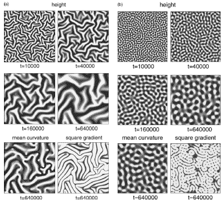
(Uchida “Orientation
order in buckling elastic membranes” Physica D 205 267-274
2005)
Some of these simulated shapes have been observed in a different
context. A elastomer substrate whose top layer undergoes volumetric
expansion from oxygen plasma exposure displays “complex yet
periodic wavy structures”:
(Chua et al. “Spontaneous
formation of complex and ordered structures on oxygen-plasma-treated
elastomeric polydimethylsiloxane” Applied Physics Letters 76
721-723 2000)
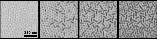
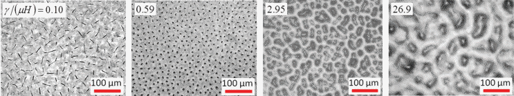
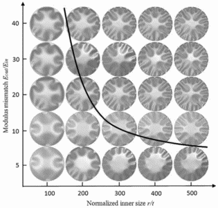
Chan and Crosby made a phase map of these features as influenced by the oxidation time and region size:
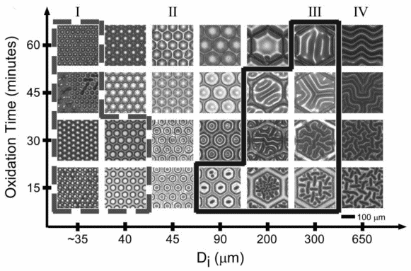
(Chan et al. “Fabricating microlens arrays by surface wrinkling” Advanced Materials 18
3238-3242 2006)
At this point it's probably time for a shar pei (“sand [i.e., rippled] skin”):
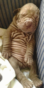
(Instagram 2016)
“Skeletal wrinkles” appear when the
hexamine solvent is evaporated during zinc
oxide sol-gel preparation:
(Kwon et al. “Wrinkling
of a sol-gel-derived thin film” Physical Review E 71
011604 2005)
...and ridges of deflated PDMS are shown in these micrographs of the canonical buckling model—a film that's too big for its environment:
(Jin et al. “Mechanical instabilities of soft materials: creases, wrinkles, folds, and ridges” PhD thesis, Harvard 2014)
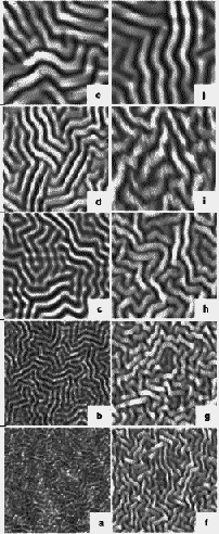
Straight-sided wrinkles evolve into “worm-like” buckling patterns in a sub-100 nm sputter-deposited stainless steel layer atop polycarbonate:
(Claymand et al. “Experimental investigation of the instability of buckling patterns: From straight-sided to wormlike structures” Scripta Materialia 44
2623-2627 2001)
Similar features have also been described as “telephone cord buckles”:
(Moon et al. “An experimental study of the influence of imperfections on
the buckling of compressed thin films” Acta Materialia 50
1219-1227 2002)
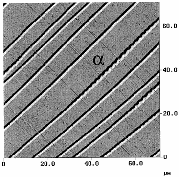
Claymand et al. called their row of buckled gold film features a “quasiperiodic varicose” pattern:
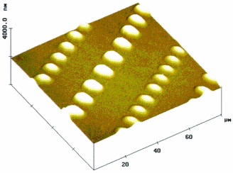
(Claymand et al. “Atomic force microscopy investigation of buckling
patterns of nickel thin films on polycarbonate substrates” Philosophical Letters 82
477-482 2002)
“Herringbone” shapes appear when a gold film is cooled
after deposition on PDMS:
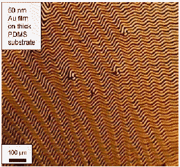
(Chen et al. “A family of
herringbone patterns in thin films” Scripta Materialia 50
797-801 2004)
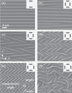
...and a disorganized array of herringbones is termed a “segmented labyrinth”:
(Cai et al. “Periodic patterns and energy states of buckled films on
compliant substrates” J Mech Phys Solids 59
1094-1114 2011)
Separated segments are described as exhibiting a “peanut” morphology:
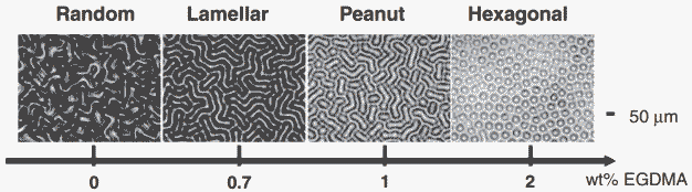
(Yang et al. “Harnessing surface wrinkle patterns in soft matter” Adv Funct Materials 20
2550-2564 2010)
Under other conditions, the same report by Yang et al. presents “ripples”:
Permanent wrinkles are seen in a free-standing boron nitride
film after its salt support is dissolved away:
(Coupeau et al. “Evidence
of plastic damage in thin films around buckling structures”
Thin Solid Films 469-470 221-226
2004)
...and casein gels exhibit still more features similar to what I saw in suspended metal films:
(Leocmach et al. “Hierarchical wrinkling in a confined
permeable biogel” Science Advances 1
e1500608 2015)
“Creases” and wrinkles appear when an elastomer is affixed to a relatively rigid substrate using an electric field:
(Wang et al. “Creasing-wrinkling transition in elastomer films under electric fields” Phys Rev E 88
042403 2013)
Finally, “undulations” and “cracks” are fabricated:
(Guvendiren et al. “Solvent induced transition from wrinkles to creases in thin film gels with
depth-wise crosslinking gradients”
Soft Matter 6 5795-5801
2010)
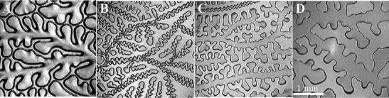
Thin Film Dewetting
We now turn to the
dewetting of liquids, sometimes modeled as a decomposition into wet
and dry phases. Anshutosh Sharma of the Indian Institute of
Technology describes dewetting morphology:
As
the film thickness is increased, the initial pathway of
evolution changes from the formation of small spherical droplets, to
long mesas (parapets) and islands, to circular holes, all of which
eventually resolve by ripening into a collection of round pancakes at
equilibrium. However, beyond a certain transition thickness, a novel
metastable honeycombed morphology, resembling a membrane or a slice
of Swiss cheese, is uncovered, which is produced by an abrupt
“freezing” of the evolution during hole growth.
(Sharma et al. “Pattern
formation and dewetting in thin films of liquids showing complete
macroscale wetting: from ‘pancakes’ to ‘swiss
cheese’” Langmuir 20 10337-10345
2004)
Leonard Schwarz at the University of Delaware dried a thermosetting polymer on an inked aluminum sheet. His group observed “particular
patterns of holes, ridges, filaments, and, ultimately, droplets”
both in experiments and in simulations:
(Schwartz et al. “Dewetting
patterns in a drying liquid film” J Colloid Interface Sci 234
363-374 2001)
Observers of drying water films report the appearance of “star-like
formations” and “parabolic dendrites” as dry
patches nucleate:
(Samid-Merzel et al. “Pattern
formation in drying water films” Physica A 257 413-418
1998)
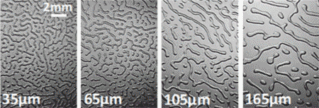
...and
“fingering instabilities” are seen as viscous polystyrene
dewets from an octadecyltrichlorosilane-coated
silicon wafer during annealing:
(Reiter,
“Unstable thin polymer films: rupture and dewetting process,”
Langmuir 9 1344-1351,
1993)
Much later, Manoj Chaudhury performed an extensive study of fingering instabilities, including the “debonding, sliding, peeling and the healing of a blister,” producing spectacular
images such as the following:
(Chaudhury et al.
“Adhesion-induced instabilities and pattern formation in thin films
of elastomers and gels”
Eur Phys J E38 82
2015)
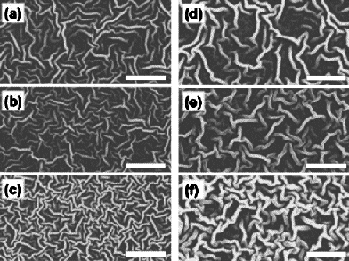
Thin Film Deposition
When silver is sputtered onto a layer of silicone oil, the initial
sputtered atoms are driven into the top layer of the oil. At some
percolation threshold, a “branched structure” consisting
of silver clusters nucleates:

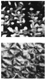
(Ye et al. “Structural
and electrical properties of a metallic rough-thin-film system
deposited on liquid substrates” Phys Rev B 54 14754-14757
1996; Feng et al. “Growth
behavior and surface morphology of Ag rough films deposited on
silicone oil surfaces” Thin Solid Films 342 30-34
1999)
I’ve
included these silver features because of their visual appeal;
however, it’s important to note that their origins are more
complex than the other patterns shown previously. All of the earlier
patterns are caused by imposed or internal compressive stress (in the
case of the buckled films) or surface-volume energy tradeoffs (in the
case of the dewetting films). In contrast, the sputtered silver film
morphology is attributed to mixing of the
silver atoms with the silicone oil layer.
From Science to Engineering
Scientists necessarily use tools to learn more about nature; engineers necessarily learn about nature to develop better tools.
Starting around 2007, reports of thin film deformation by liquids, the phenomenon that so mystified me, exploded in the literature. It started with Huang et al.'s report of "Capillary wrinkling of floating thin polymer films" in Science:
(Huang et al. “Capillary wrinkling of floating thin polymer films”
Science 317 650-653
2007)
Suddenly, a new field—elastocapillarity—was emerging. Enrique Cerda, one of the coauthors, had done his postdoc with Mahadevan at Harvard with a heavy concentration on wrinkling; in fact, Adam Zeiger and I cited one of their papers in the
context of cell-contraction-induced wrinkling of a thin silicone film.
Here, I was circling back to thin film patterns from a different direction—animate actomyosin-generated buckling via live cells:

(Burton et al. “Keratocytes generate traction forces in two phases”
Mol Biol Cell 10 3745
1999)
Surface instabilities were a hot topic (you know you've made it when your field gets surveyed in MRS Bulletin):
(Wang et al. “Beyond wrinkles: Multimodal surface
instabilities for multifunctional
patterning”
MRS Bulletin 41 115-121
2016)
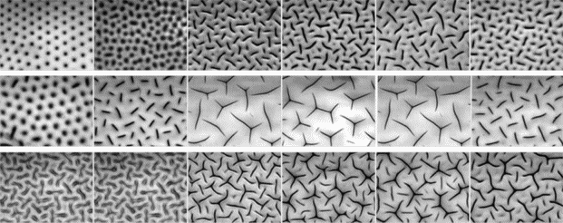
...and Wang and Zhao provided a phase map of morphologies:
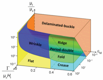
(Wang et al. “A three-dimensional phase diagram of
growth-induced surface instabilities”
Scientific Reports 5 8887
2015)
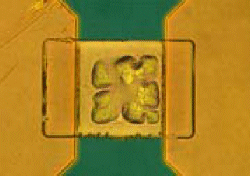
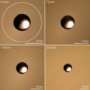
With this explosion of new research, I found some more close matches to the localized floral patterns I saw in my sub-micron-thick suspended Ti/Au/Ti membranes 50 μm on a side:
(Yan et al. “Spontaneous wrinkling pattern of a constrained thin film
membrane”
Applied Physics A 107 761-767
2012)
Still other reports have described tents, branches, tubes, sawteeth, shrivels, wavy leaves, ruga, furrows, curtains, and—one of
my favorites so far—wrinklons! Sure, let's coin another word, given the obvious paucity of the language to describe these features.
The
large number of reports in the literature and the frequency of
rediscovery of these patterns shown above (and there are many more,
similar, patterns not included here) suggest that an atlas of
patterns would be helpful to researchers. Because of the evocative
descriptions found so far, I am awaiting the discovery of additional
reports of crinkles,
nodules, buttons, indents, grooves, puckers, scabs, scales, depressions, notches, slashes, serrations, channels…scallops…corrugations…crenulations…