And now, a quick overview of a recent prototyping project involving machining, polishing, and circuitry: brass initials configured
to trigger pulsed LEDs in an acrylic base by a magnetic switch.
Much of this work
was executed at Ace Monster Toys,
a hackerspace/makerspace in Emeryville, California, with a nice set of prototyping facilities: milling,
turning, 3D printing, laser cutting, electronics assembly, woodworking,
and textiles.
Inspiration and constraints
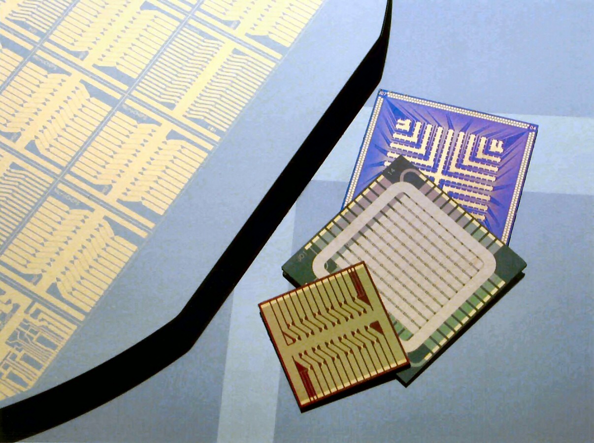
In my microfabrication days, I got to make great mirrors: wafers with a thermally or e-beam-evaporated metal layer, maybe a micron thick, that
would emerge from a vacuum chamber looking absolutely perfect and ready for chemical etching to form circuitry, as exemplified by these wafers and chips that I
prototyped at MIT's Microsystems Technology Laboratory for MicroCHIPS:
Of course, the prerequisite for such high-quality specular reflection is a silicon substrate that comes out of the box
with a roughness of a nanometer at most.
I hadn't explored the top-down approach—successively polishing a rough surface—and
this video by Clickspring
made it look straightforward.
After polishing with a succession of sandpaper grits up to 5000 and then an abrasive compound, the eye can't distinguish any surface features,
producing an acceptable mirror. I wanted to try this out.
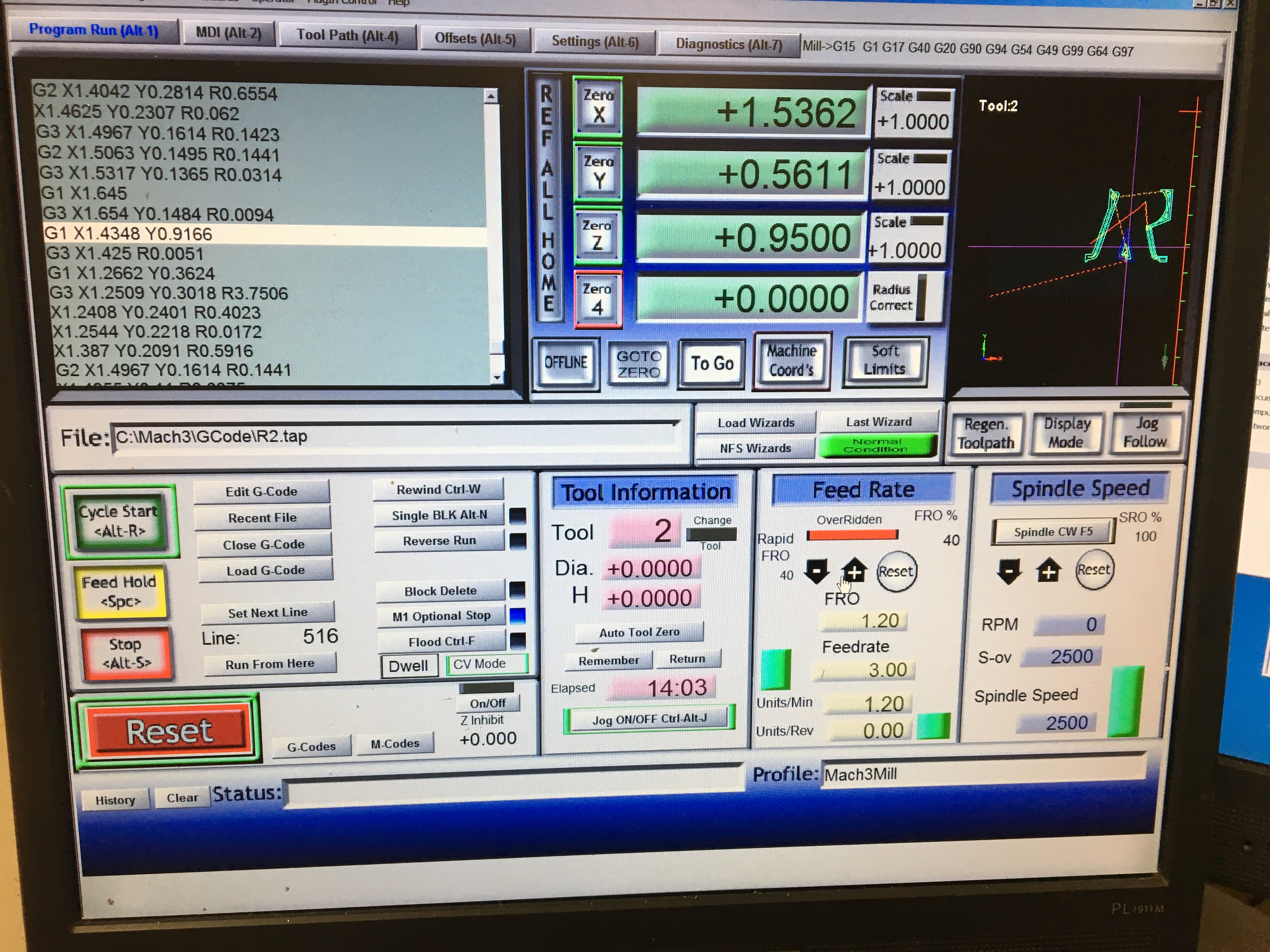
For the first step of rough machining,
AMT had a Mach3D mill that could accommodate a workspace of (only) about 12″ × 5″; happily, though, it was a CNC tool that accepted
G code. I hadn't worked with
CNC before, so I wanted to make something that was impossible to hand-machine. Letters (e.g., initials) seemed ideal for a prototyping demonstration. Brass (specifically, so-called free-machining brass) would be the easiest metal to work with and would carry a reddish gold lustre upon polishing.
Once I thought of using an acrylic disc as a base to hold the letter
vertically, it seemed natural to use magnets
to keep the letter upright (on its own, brass isn't magnetic), inspiring the idea of incorporating some type of circuitry to sense the magnetic field and activate
eye-catching LEDs.
A battery measuring a cm3 in volume can power a typical LED for a few days at most, though, so I couldn’t have several LEDs staying lit constantly after the letters were positioned in place; the LEDs would have to be modulated by some type of
blinking or temporary activation to provide long-term operation.
A quick discharge through one or more capacitors seemed like an ideal way to produce a low-key light show.
Design
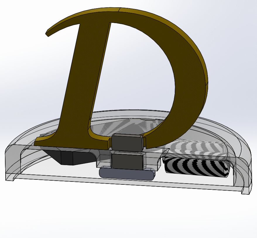
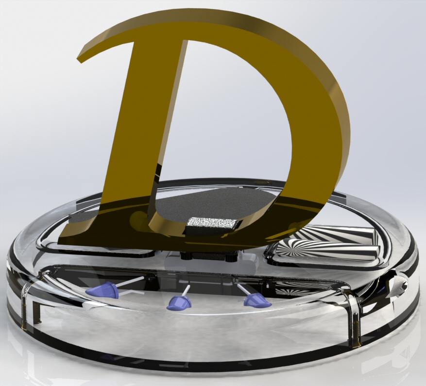
These renders were done in SolidWorks (the free alternative is AutoDesk's
Fusion 360). Here, a magnet mounted in the brass letter is attracted to an adjacent bar of stainless steel mounted in the base and triggers an underlying reed magnetic sensor. Shown in
zebra coloring are capacitors that are alternately charged by coin batteries (in the thin black case on the lower left) and discharged into three LEDs.
The supplier Digikey now has an app for designing schematics:
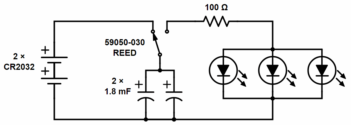
The reed switch switches from charging two 1.8 mF capacitors from a couple of 1.5 V CR2032 coin batteries to
dumping the capacitive energy into three blue LEDs through a 100 Ω resistor. The resistor protects the LEDs from an excessively high current. Strictly speaking, one might want a resistor in series between the capacitor and the
batteries to avoid an instantaneous short circuit when they're connected, but the internal resistance of the battery can serve this purpose.
There are two primary ways to sense a magnetic field: a reed switch (elongated, moving parts) and a Hall effect sensor (compact, solid state).
Both are annoyingly directional, and Hall effect switches have an annoying peculiarity that their sensitivity is manifested as
lobes that (in my configuration) would activate the switch when the letter was an inch away but disable it when the letter
was directly overhead.
In the end, I converged on using a magnet with horizontal N-S orientation and activating a reed switch about 1/2″ away.
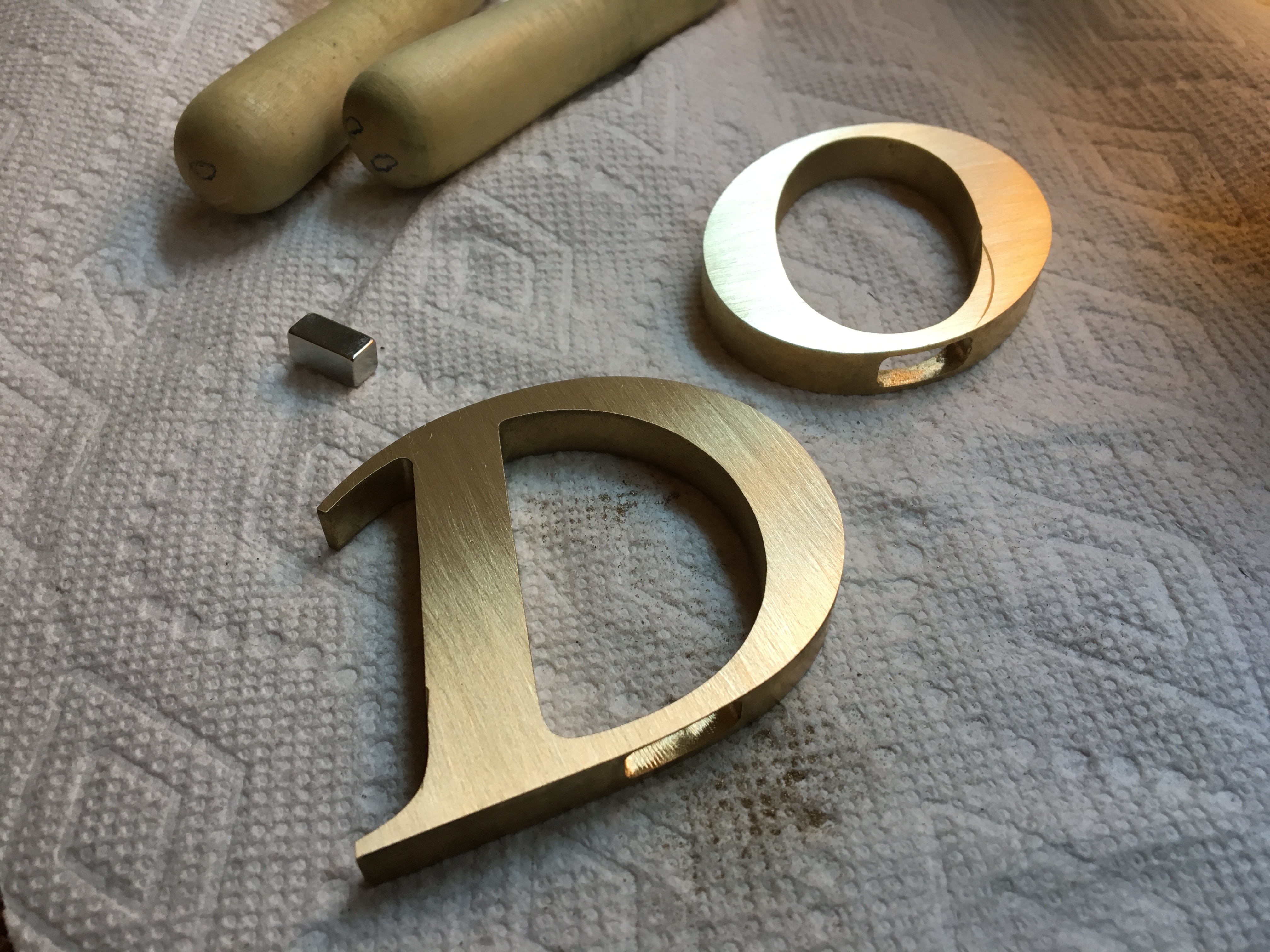
The magnet strength was as issue. A 1/16″ × 1/16″ × 1/4″ magnet (from K&J Magnetics,
which Katie says should be our favorite company) would fit
almost entirely within certain letters but wasn't strong enough to activate the reed switch. I ended up using a 1/4″ × 1/4″ × 1/2″
B448-N52, high-grade NdFeB (NIB), which can hold up to about 6 lbs adjacently. Separated by some intermediate acrylic, the actual pull force ended up being somewhat less than a pound, which was a perfect compromise between being too weak
to keep the letters upright and too strong to easily detach.
According to Digikey, the reed switch triggers at 20 ampere turns, or about 20 Gauss, and the selected magnet exerts a surface field of 7000 Gauss, maybe 100 Gauss an inch away. So triggering wouldn't be a problem. The magnet would be attracted to a 1/4″ × 1/4″ × 3/4″ piece of (magnetic)
400-series stainless steel that I'd machine separately.
The 1/2″ thickness of the acrylic disc ended up constraining another aspect of the design. I wanted the LEDs to pulse for a second or so after the letter
was brought nearby; this much energy would require several mF and capacitors at least 10 mm thick. Two 1.8 mF caps wired in parallel would tightly fit into a pocket milled into the base.
Milling
A brass letter 2 1/2″ wide (corresponding to the letter height) and 3/8″ thick was a good starting point in terms
of cost and milling machine capacity. I bought the brass and most of the tools from McMaster Carr.
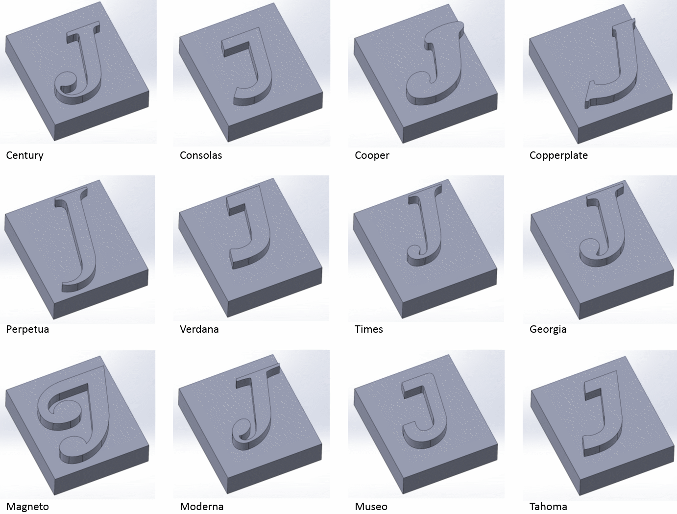
It was straightforward to try out
different fonts in SolidWorks and generate the associated CAM G code. Here's an example:
(DO)
(T2  D=0.125 CR=0. - ZMIN=-0.4 - FLAT END MILL)
G90 G94 G91.1 G40 G49 G17
G20
G28 G91 Z0.
G90

(2D CONTOUR1)
M5
M9
T2 M6
S2500 M3
G54
M8
G0 X0.7964 Y1.7539
G43 Z0.1 H2
G1 X0.8784 Y2.1292 Z0.0664 F3.
X0.8621 Y2.1239 Z0.0649
X0.8345 Y2.114 Z0.0623
X0.8073 Y2.1034 Z0.0598…
The file continues for several thousand more lines of coordinates. The preamble specifies the following: The process name is “DO” ((DO)). The tool is (parenthetically) a 1/8″ diameter end mill ((T2 D=0.125 CR=0. - ZMIN=-0.4 - FLAT END MILL)). We use absolute positioning in machine coordinates (G90), use inches per minute as the feed rate unit (G94), use incremental arc mode (G91.1), turn off tool radius compensation (G40), cancel tool length offset compensation (G49), …
Much of this code is set by the compiler but may not have any effect on the specific tool; for example, once we start an actual cut (namely, 2D CONTOUR1), the G code specifies to stop (M9) or stop (M8) the coolant flow. This is a relic of the CAM module of SolidWorks. On the hobby-level Mach3D mill, there is no coolant. The coolant is someone holding a shop-vac nozzle nearby.
The most important commands, and the ones frequently used in manual mode, are G0 (move as fast as possible to a new coordinate location) and G1 (move at the specified cutting speed to a new location).
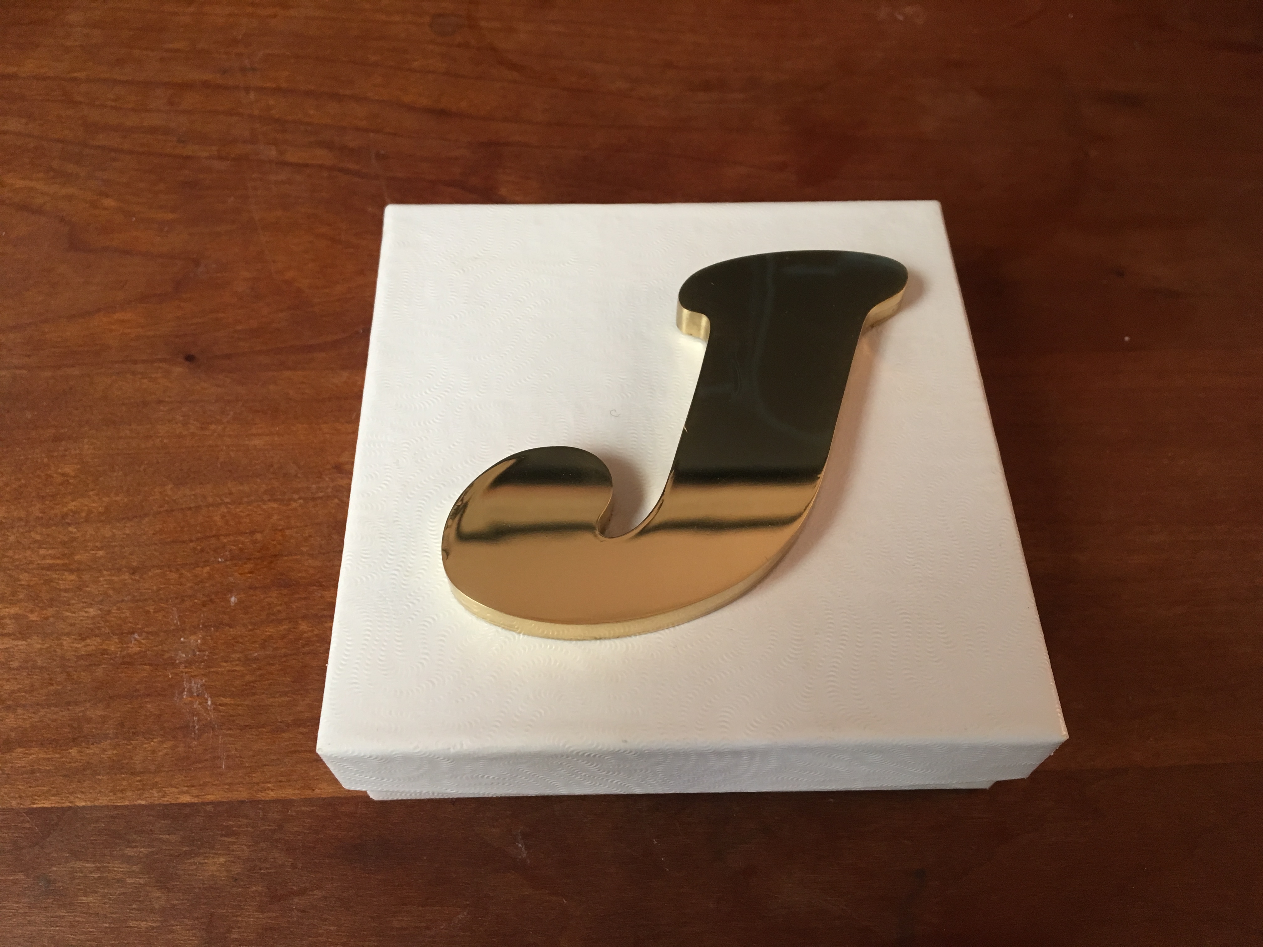
I did a few samples (a J in Cooper, after considering various other fonts, and an R in Times New Roman):
I mounted the brass (which I'd need to cut completely through) on a 1″ thick piece of aluminum using superglue (this and tape and—for the fancy
folks—a vacuum chuck are the standard approaches to mount a workpiece to cut completely through it). The brass can be detached using heat from a small
torch. Certain cutting oils attacked the superglue; fortunately, it was no problem to cut the brass dry with only forced air as a coolant.
Some of the gotchas while milling this way—from either carelessness or the constraints of a small tool—are as follows:
- Forgetting that the edge finder has a diameter (i.e., hitting 0 instead
of entering -0.1" when indicating using the edge finder).
- Running with too large a depth of cut and too long an end mill: 0.25″ and 3/4″, respectively, for a 1/8″ end mill. I broke a few end mills under routine cutting before reducing
to a 0.1″ DOC and a 1/2″ working distance end mill (some recommend a DOC of half the diameter, even more conservative).
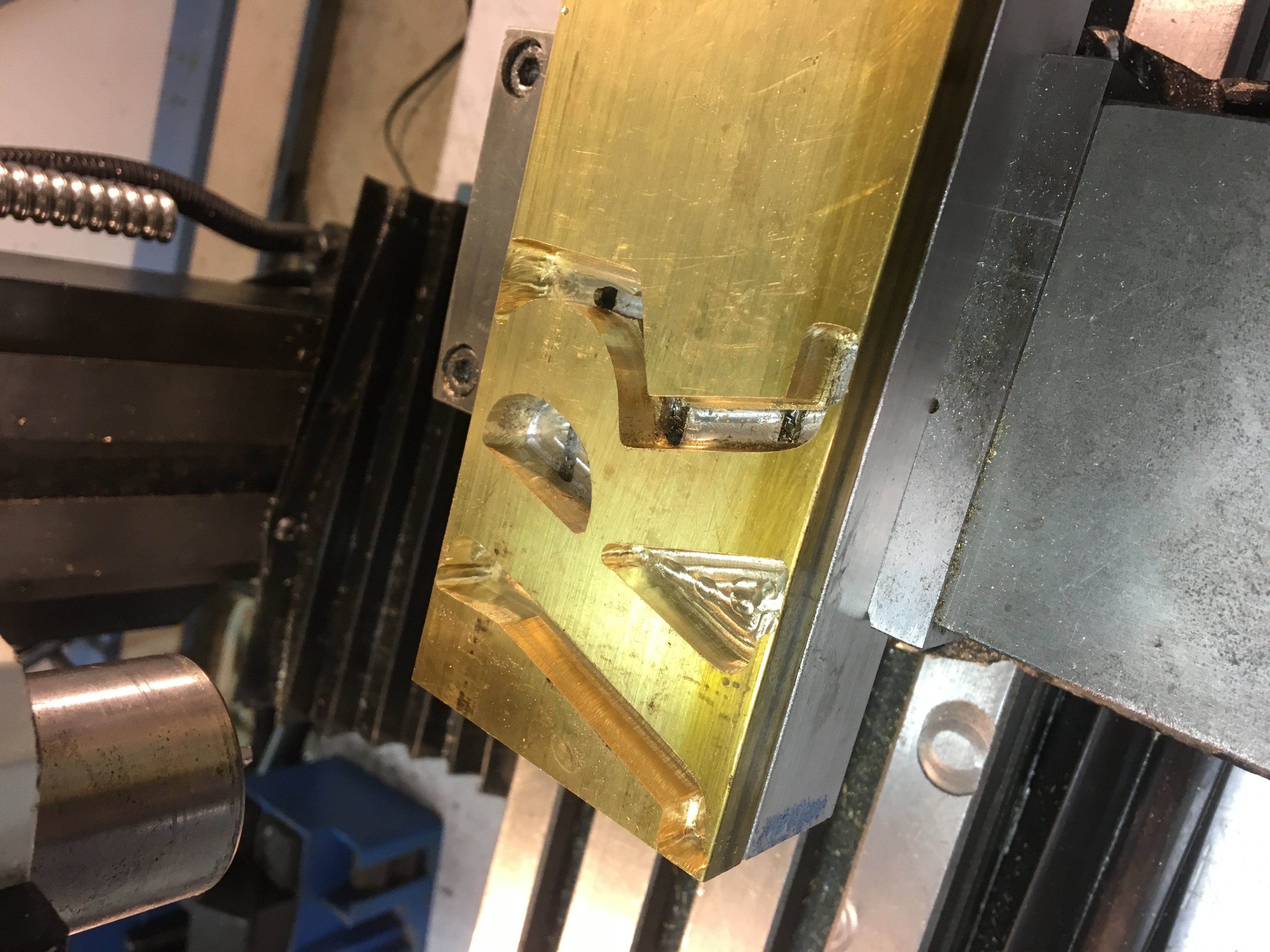
- Pausing the machine and then resuming cutting—the Mach3D would forget where it was and drive the end mill into the
piece, breaking the cutting tool or gouging the piece (or both). These defects are visible on the R piece.
- Running off the edge of the workspace. The milling program would flash “soft limits” and stop the end mill movement. It seemed like any action
except stopping, withdrawing, repositioning, and rerunning the complete program would result in the end mill jamming itself into the piece,
often breaking the mill.
OK, on to the key info: speeds, feeds, and depth of cut. The mill maxed out at 2500 rpm, lower than the typical maximum for brass with a high-speed-steel
1/8″ end mill: RPM = 4 sfm/φ, a suitable surface feet per minute (SFM) rate being around 300 for free-machining brass.
The recommended chip load of about 0.0006″ corresponds to a speed of
0.0006×2500×2 flutes, or 3 IPM, which worked well. I sucked up the chips using a shop-vac, which also provided some degree of cooling but more importantly
moved those chips away from the fragile 1/8″ end mill.
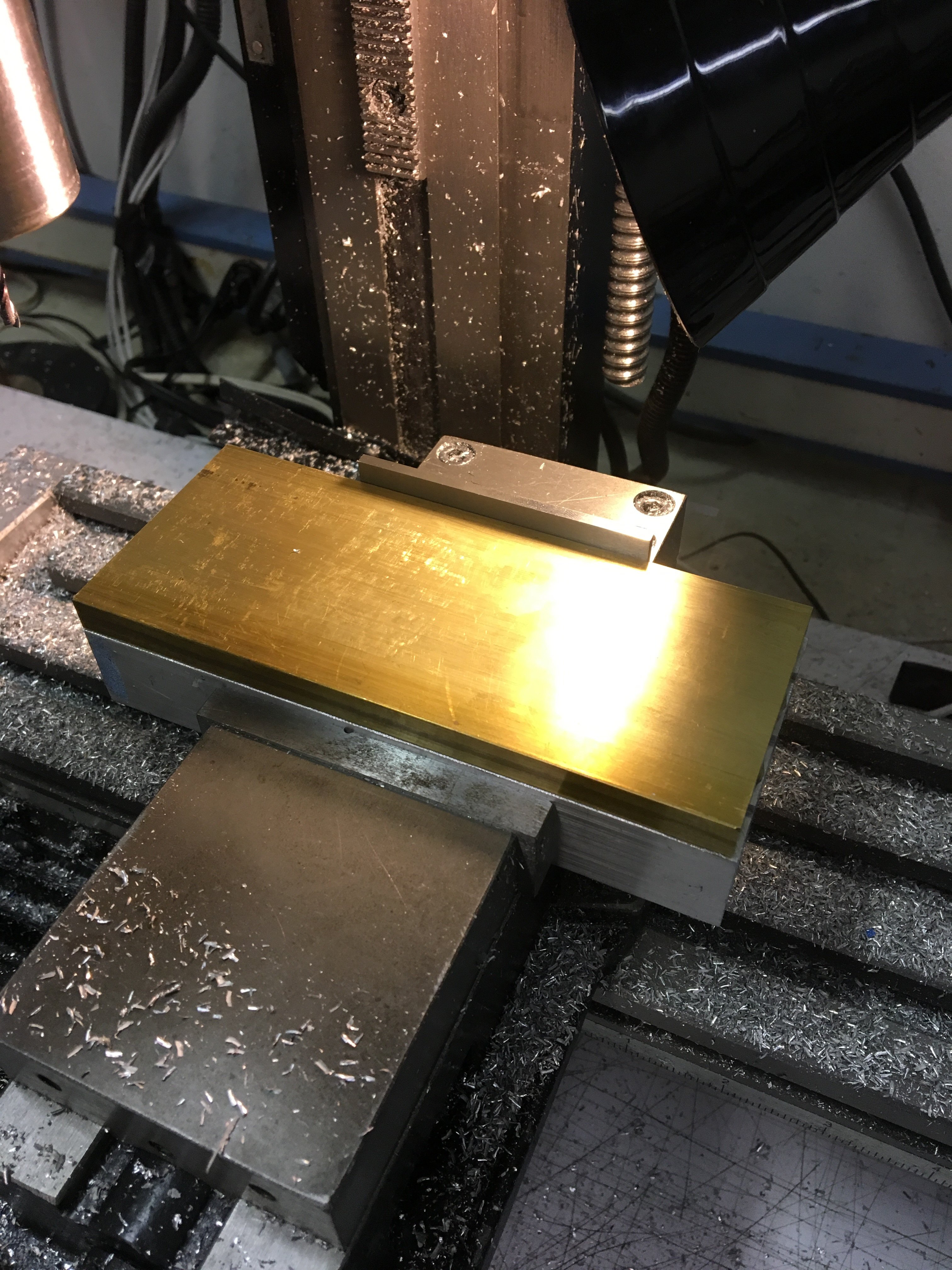
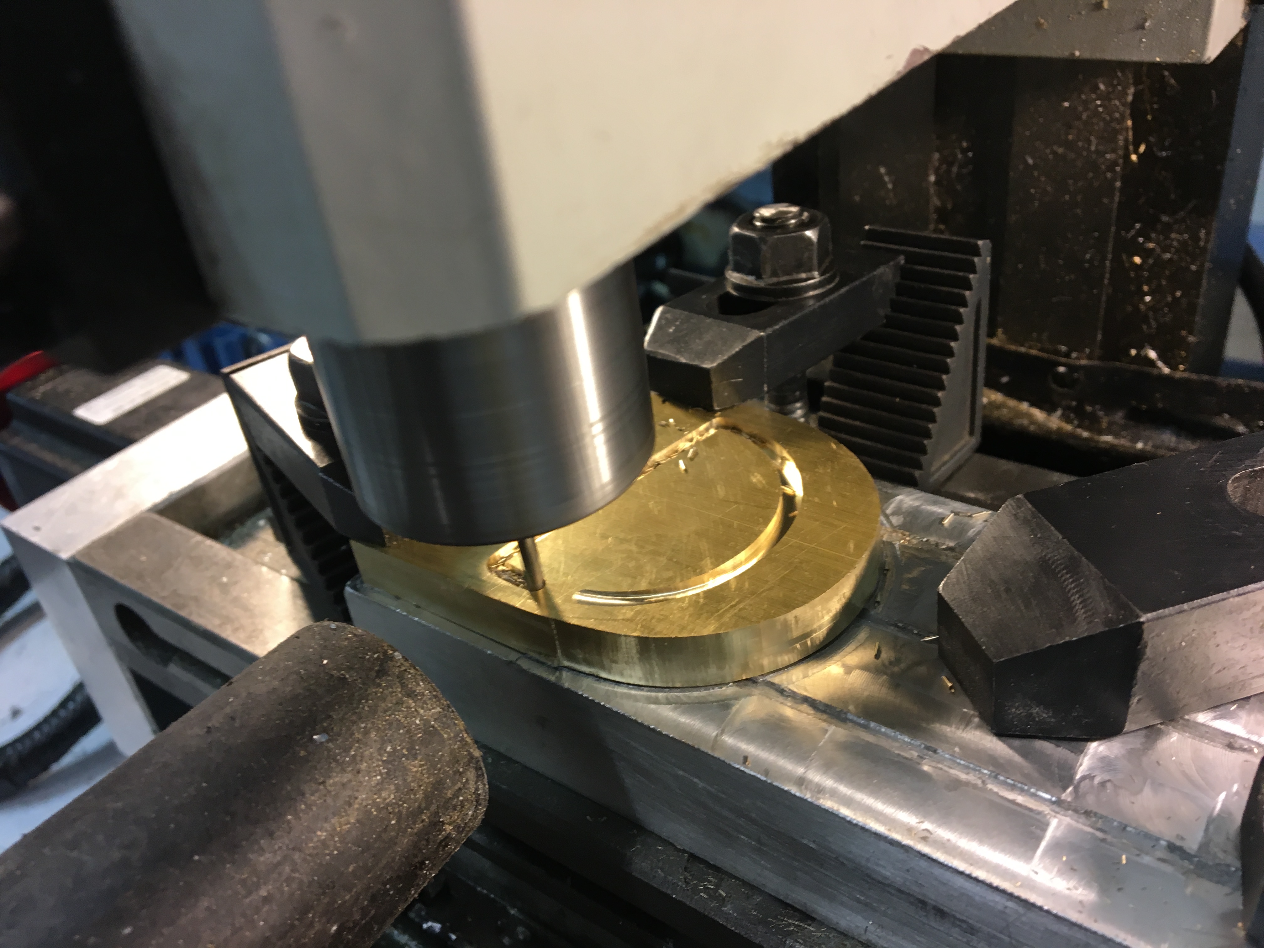
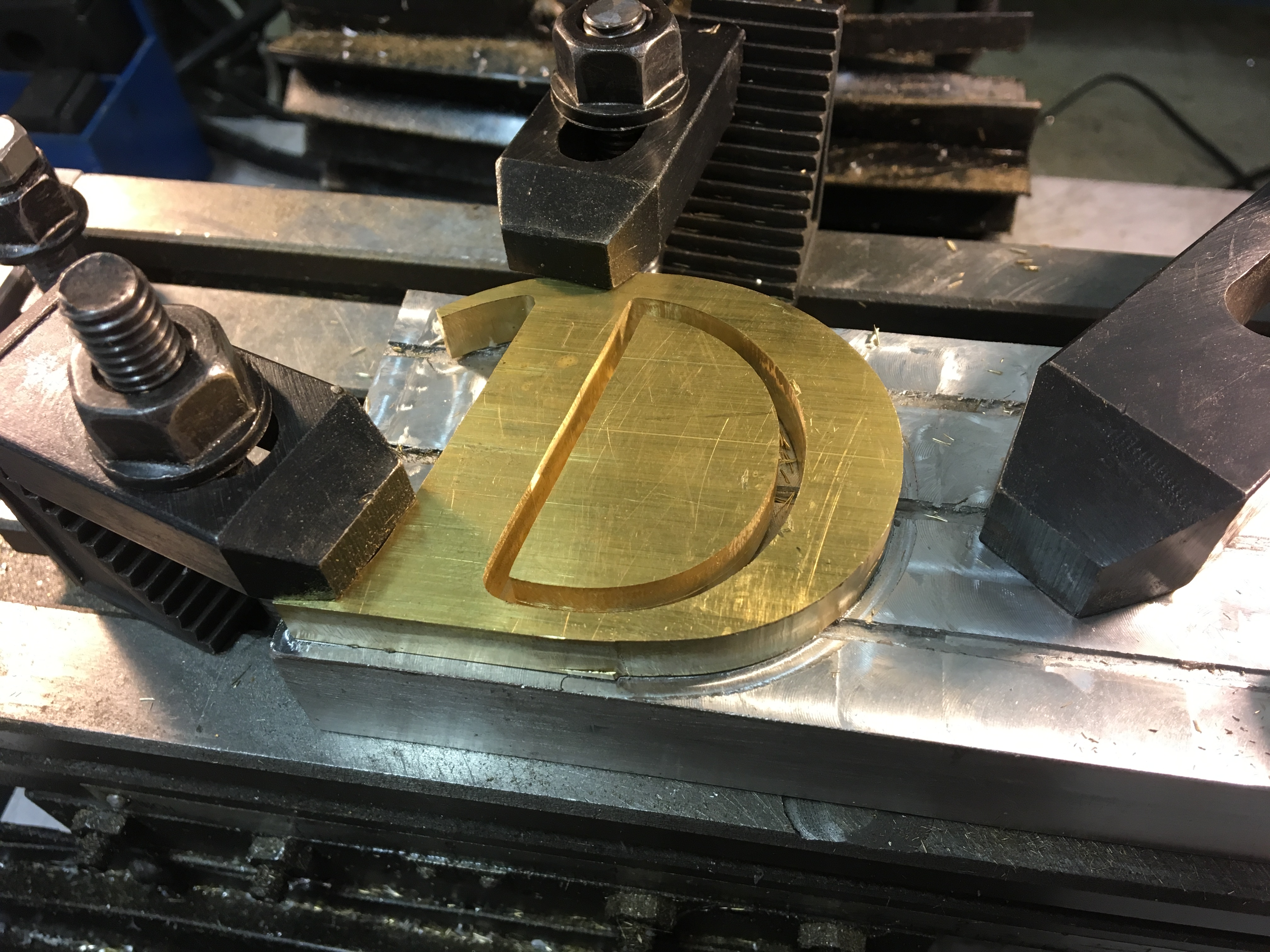
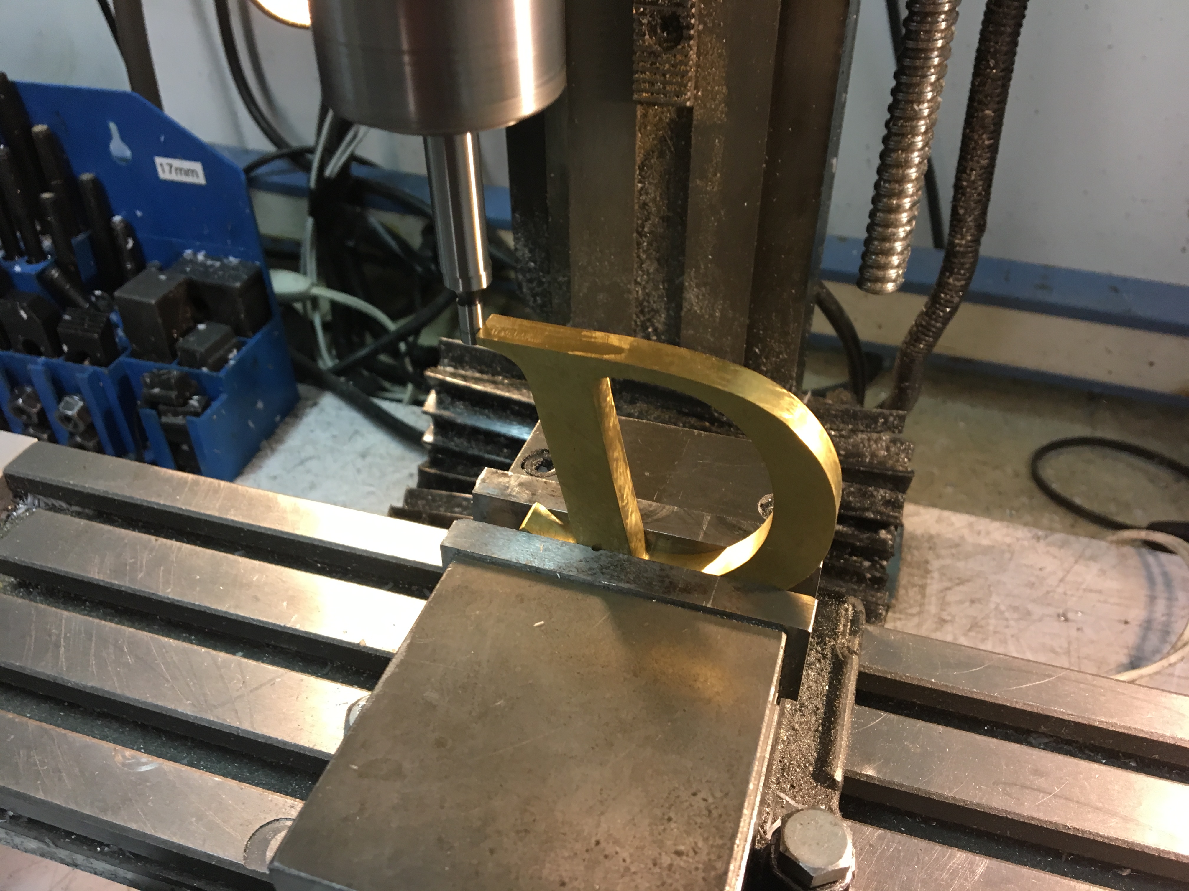
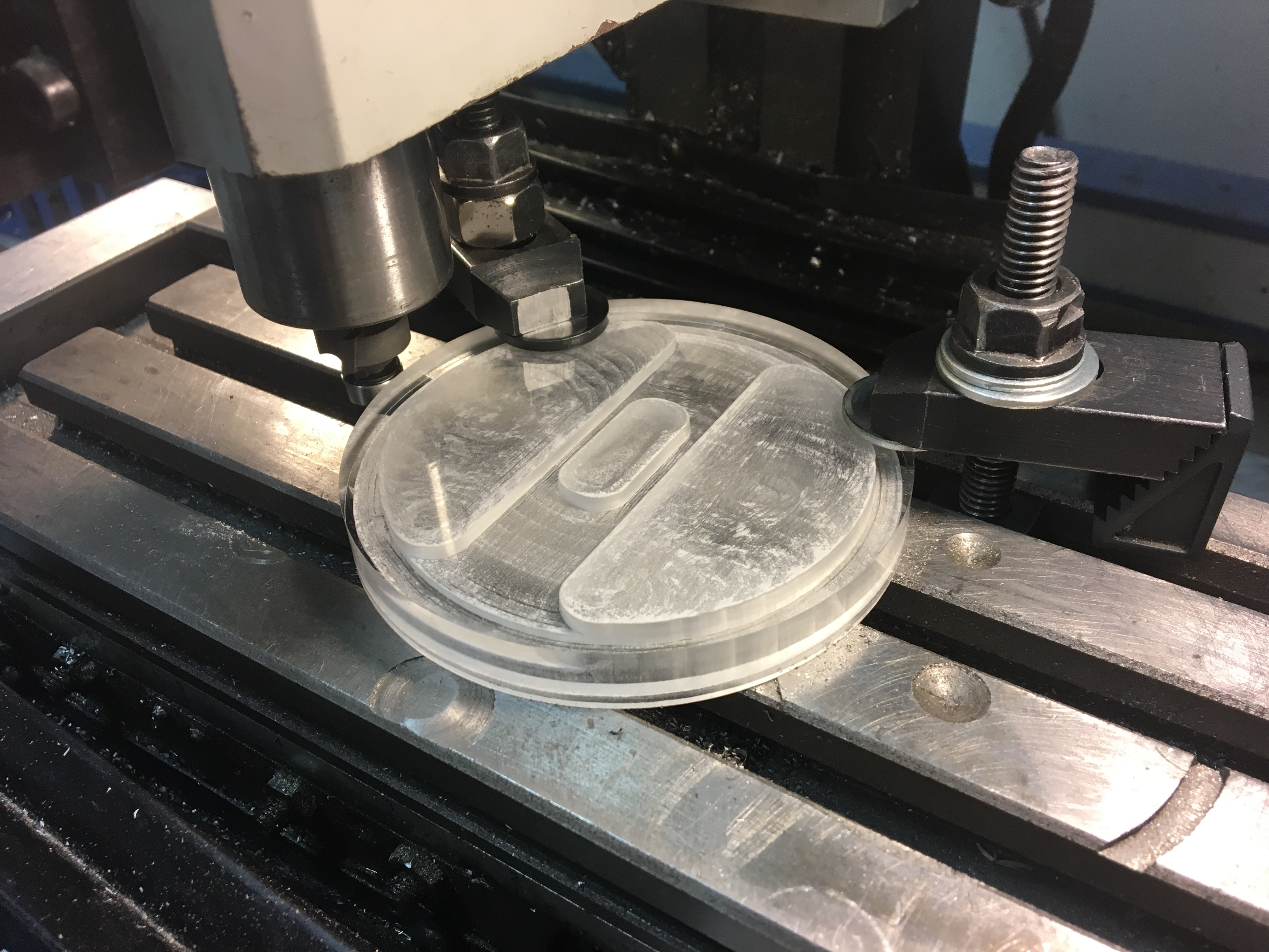
Shown below are the initial brass sheet (superglued to an aluminum base for thru-cutting), the contour being cut using the end mill, the finished cuts before the brass
is heated and dislodged from the base, and the rough sample before polishing. The initials each have a flat spot to identify a location for orthogonal milling to form the magnet pocket.
The 1/8″ end mill can’t produce internal corners any smaller than that, so it was necessary to follow up with file work to cut concave corners.
Polishing and lacquering
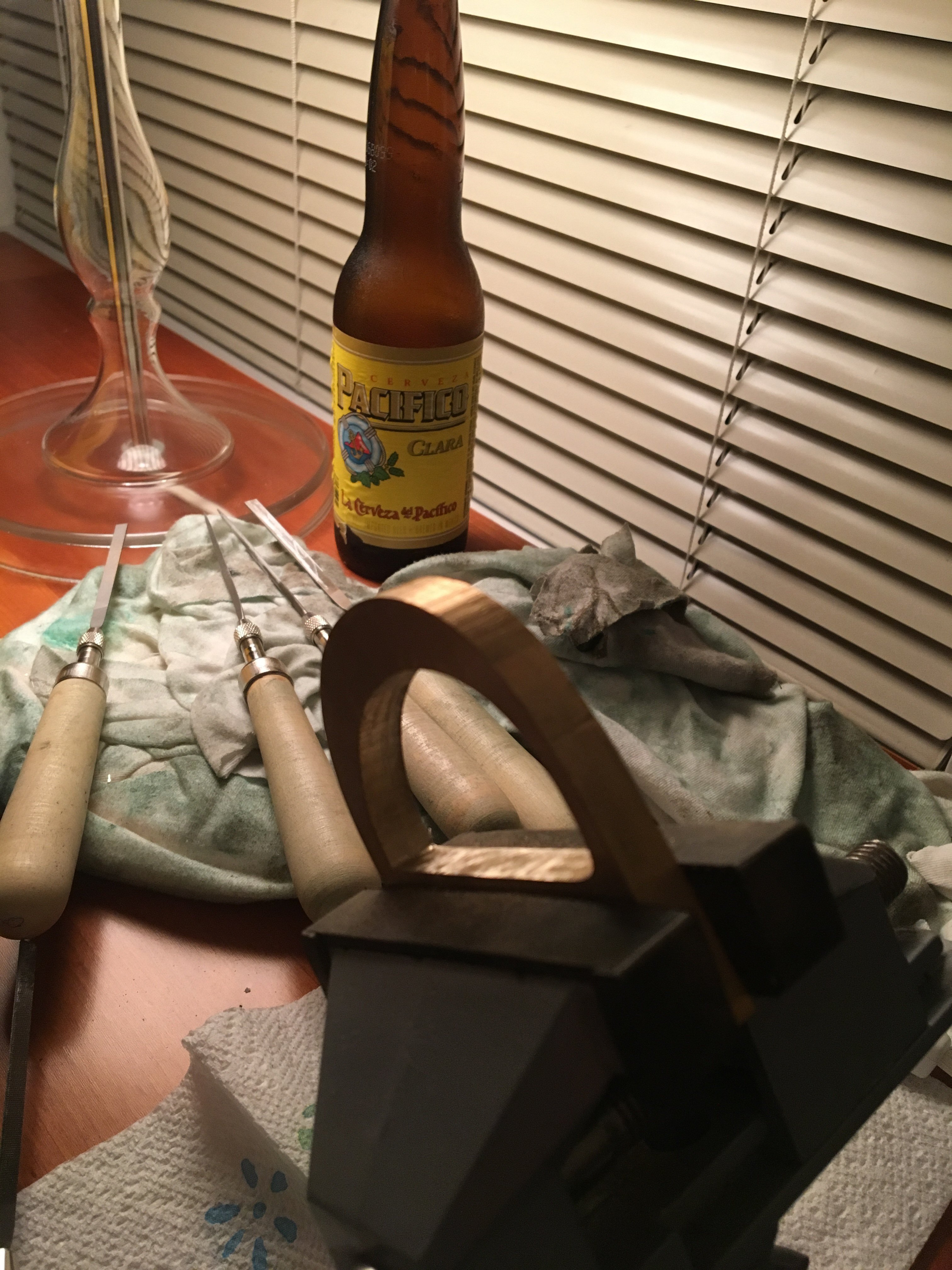
I used #00, 0, 2, 4, and 6 barrette-style Swiss files (purchased through eBay) and clamped the pieces on a little $20 vice. Brass is extremely mushy at this scale, so it's useful to powder one side of each file and
let the other side's cutting points get clogged for two different levels of abrasion. A #6 file clogged with brass abrades only minimally and can give
nearly a mirror-like finish on its own (after working through the progression of rougher files). My go-to beer during this stage was Pacifico.
The final polishing compound was a canuba-based wax formulation recommended by Clickspring.
I polished the front sides of the letters using sandpaper (200 up to 3000–5000 grit, e.g., 200, 400, 600, 800, 1200, 1500, 2500, 3000, 5000)
taped on a 12″ × 12″ × 1/2″ glass base for flatness. Dry or wet
polishing wasn't much different—either way, plenty of rinsing is required between switching grits. I switched directions by 180° when changing
grits, making it straightforward to identify when the previous polishing marks were removed. Polishing to only 100 grit on the back looked cool and was about half the effort of polishing to a mirror finish.
I initially brushed the lacquer on (with a variety of test brushes) but the results were always a little too stripy/defecty.
3:1 thinner:lacquer worked well to avoid runs, which occurred with a 1:1 mixture. Three coats worked well. There's still some solidified drips that I'd like to get
rid of. A ratio of 5:1 thinner:lacquer might be even better.
Base
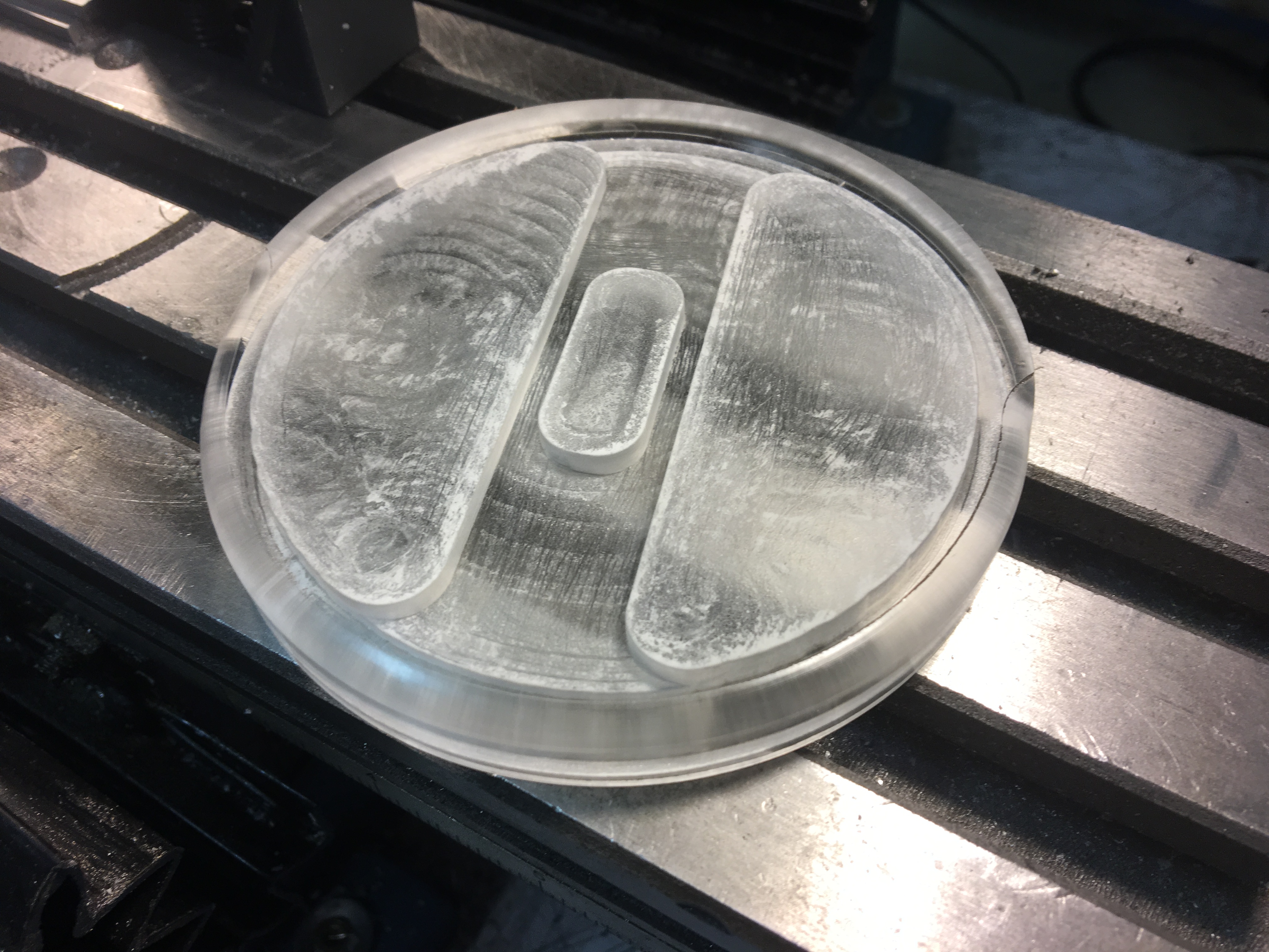
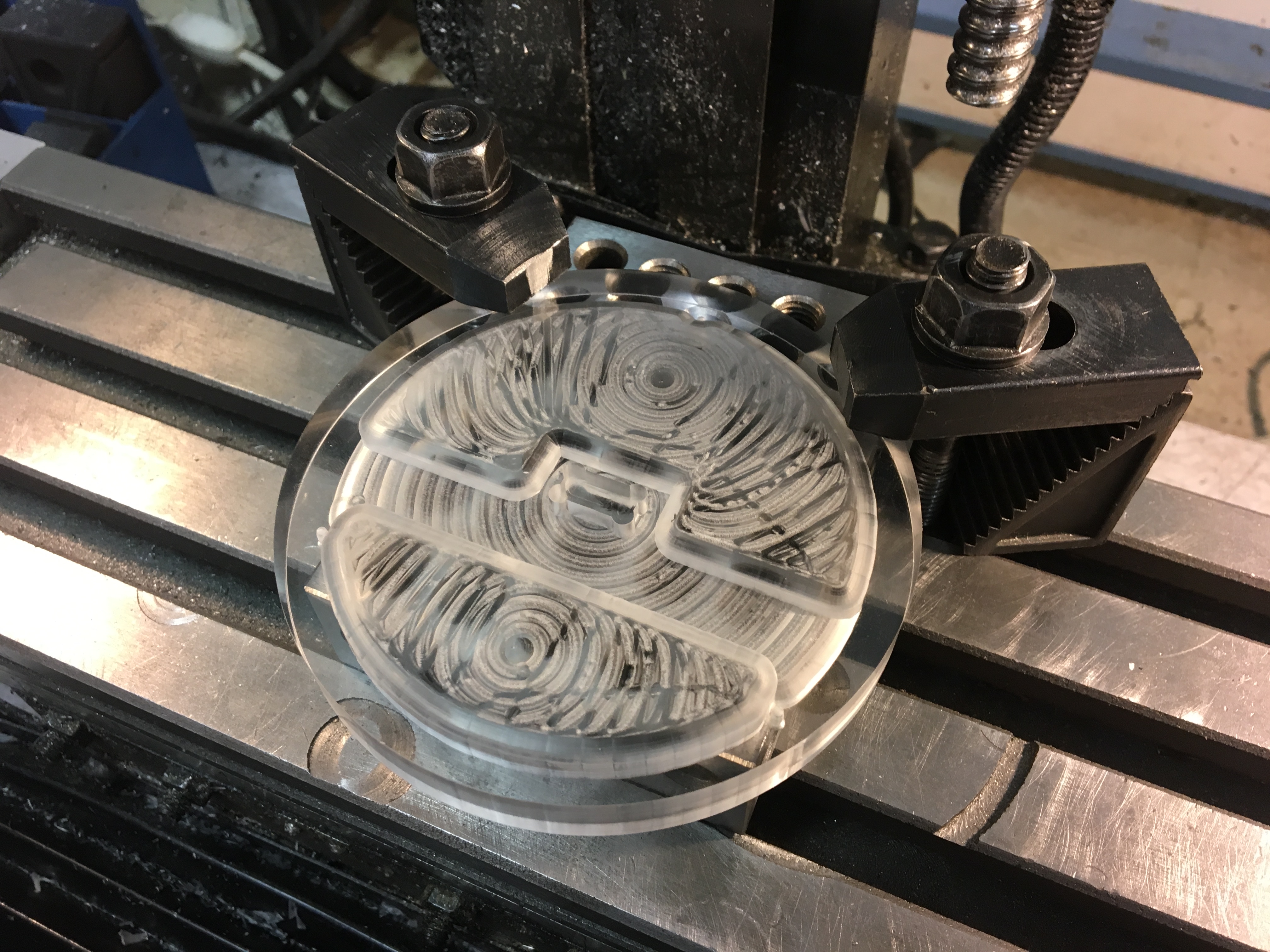
The base started out as a 4″ diameter, 1/2″ thick clear acrylic cylinder. I milled a couple internal pockets, one for the battery and capacitors and one for the LEDs; a strengthening rib separated these two areas. I used a wood router rounding bit to fillet the top edge; after doing just
one half of the circle (using the G code arc commands G02 and G03), I decided to skip doing the other side to define the front of the disc. Similar to the labor-saving step of polishing only the front of the letters, presenting a fillet cut on only the front of the base cut the work in half.
I cut the acrylic using a 7/16″ ball end mill at 1000 rpm. I used the ball end mill to avoid sharp corners in the inside cavity to avoid
the LEDs lighting random internal edges.
I had to support the piece carefully in the middle and use a gentle helical angle (5-10°) to avoid deforming the thin area that remained.
I generally cut the acrylic at a rate of 12 IPM with either WD-40 or canola oil (to produce much better tasting chips) as the cutting fluid. It’s easy to melt plastic, but one can sweep the crap away with another run.
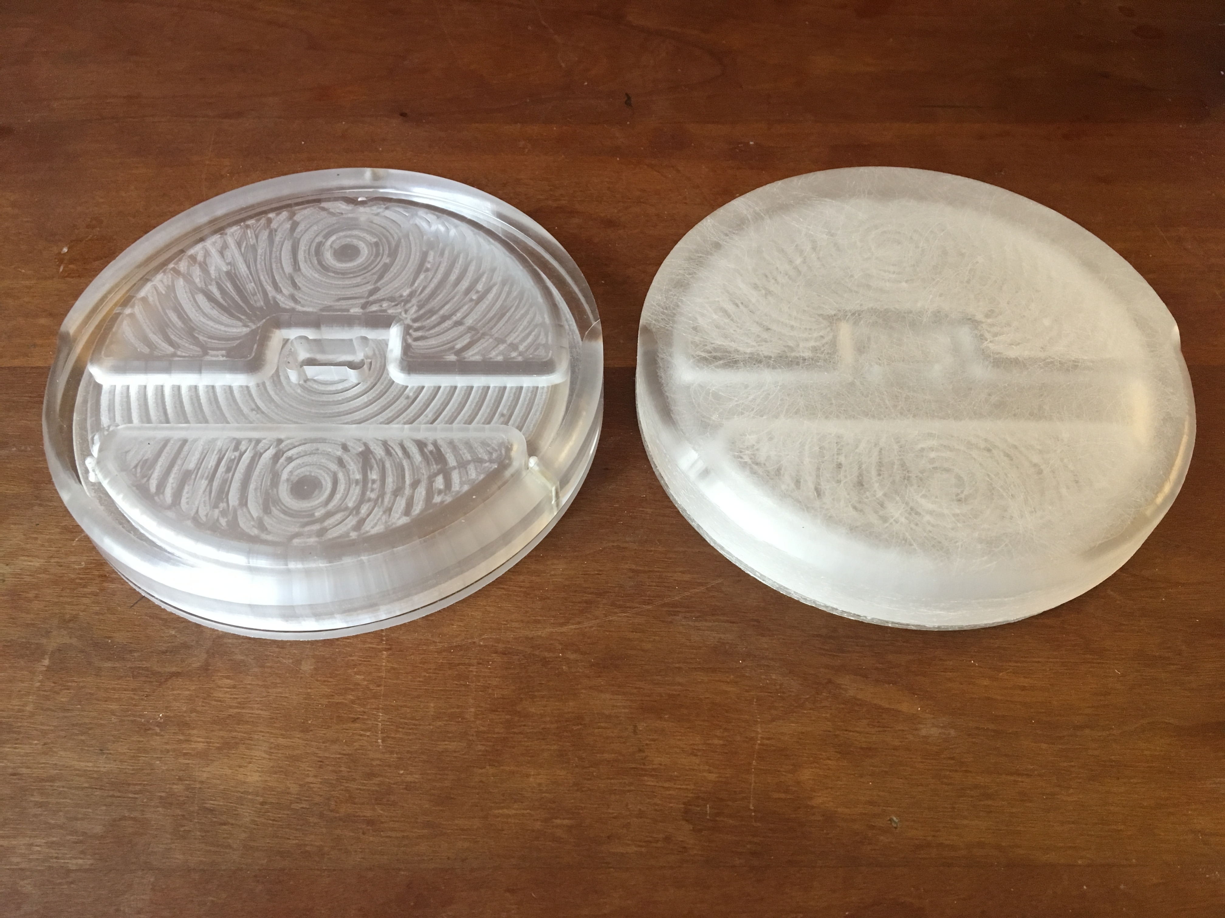
The original render showed the components clearly under the acrylic, but I preferred a diffused glow, so I roughened the (beautifully transparent, as delivered) acrylic using 60-grit sandpaper to more evenly spread the LED light.
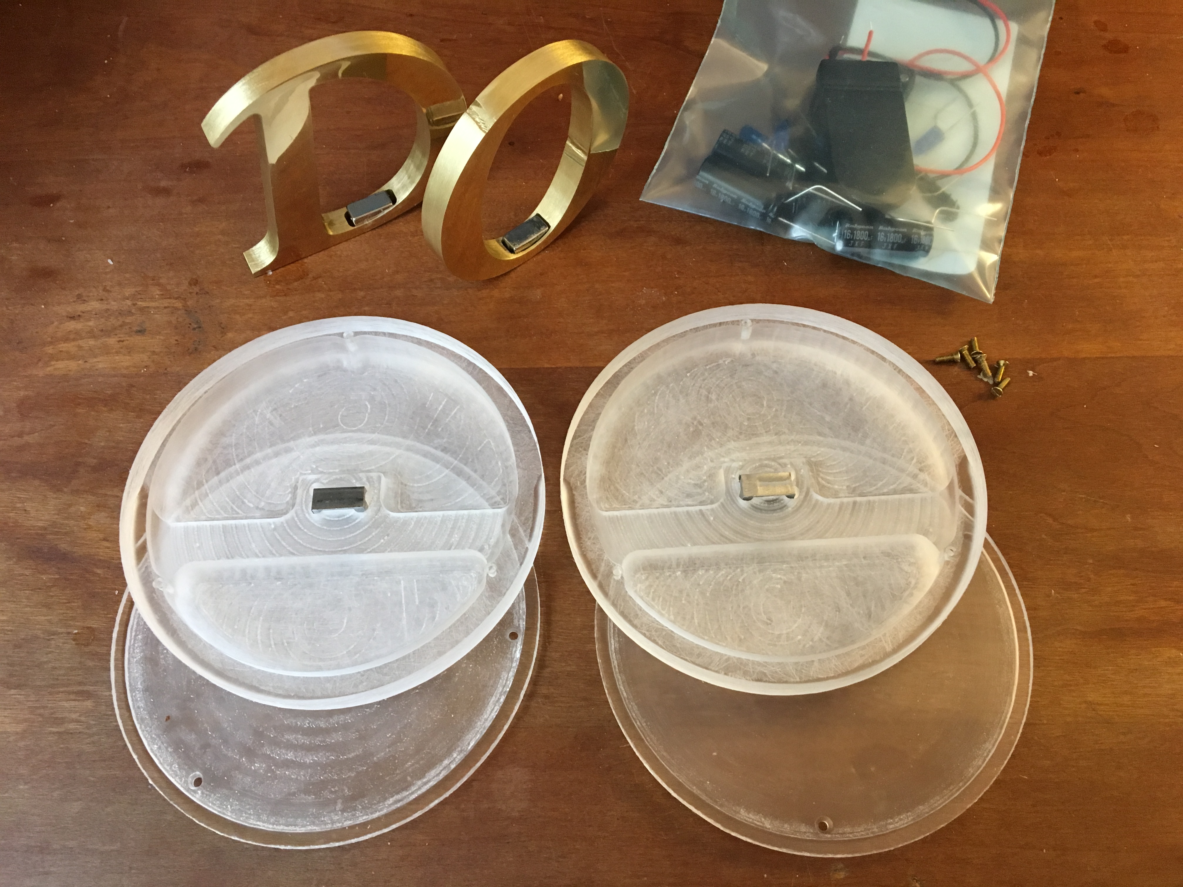
Assembly
I messily hot-glued the components into place (the step I’m least satisfied with, since the glue was visible from the opposite side).
There’s a thin back piece that screws on with 1-72 brass screws, which let me practice countersinking. Here, the clearance screw was the standard #53,
and I ran the 82° countersink to a depth of the screwhead diameter: 0.137″ × 0.575 = 0.079″, where the 0.575 comes from the angle
of the countersink. To tap the 1-72 thread, I needed a #46 jobber bit (0.081″).
Now, no fragile bit survives a shared shop, and everything under 1/4″ at AMT was missing,
but I got lucky because a standard #2 centerdrill has a diameter of 5/64 = 0.078″—close enough.
Summary
A surprising discovery from working on this project was that scientific research and metal polishing occupy two completely different parts of my brain:
frequently I'd work on materials science or biotech research or technical editing until I couldn't read another word, then swivel around and work on a few cm3 of brass using a succession
of Swiss files and sandpaper for hours, turning back to the former subject to feel completely refreshed. It's just two different ways of aiming for
high-quality work.