Overview
The idea is simple: fabricate a beam
connected to two anchors. When a voltage is applied to the beam,
the flow of current causes it to heat up, expand, and deflect:
The center of the beam is
offset slightly to control the direction of deflection. The beam
deflects far more than it would if it were simply cantilevered
from a single anchor. The amplification factor can be calculated
by using concepts from solid mechanics.
We designed and fabricated
high-aspect-ratio thermal actuators from single-crystal silicon
using deep reactive ion etching (DRIE). These images show the actuators at work:
(Animation created by
using thermomechanical models in ANSYS 5.5; videos
recorded from a CCD camera mounted on a
probe station.) We go from the operational concept to a single 1 mm beam to arrays of beams, then to linear motors containing sliders nudged along by arrays.
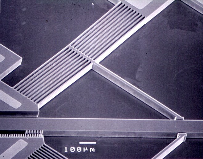
The actuators are fabricated
from silicon-on-insulator (SOI) wafers using metallization,
DRIE, and HF etching. The HF etch is timed to release the beams
without completely undercutting the large anchors. Gold pads on
the anchors provide electrical connectivity. Vernier gauges are
attached to the actuators to permit deflections to be measured.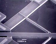
High-aspect-ratio actuators
fabricated with DRIE can generate significantly higher forces
than surface micromachined polysilicon thermal actuators.
Additionally, problems such as stiction and out-of-plane bowing
are avoided. We have demonstrated deflections exceeding 25
µm and forces exceeding 2.5 mN for a current input of 20 mA.
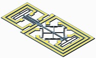
We have focused on V-beam
actuators for motor applications because these actuators produce
translational motion only, as opposed to the coupled
translational and rotational motion produced by U-beam actuators.
When fabricated in parallel arrays and connected by a center
yoke, as shown in the video above, the resultant force scales up
with the number of actuators.
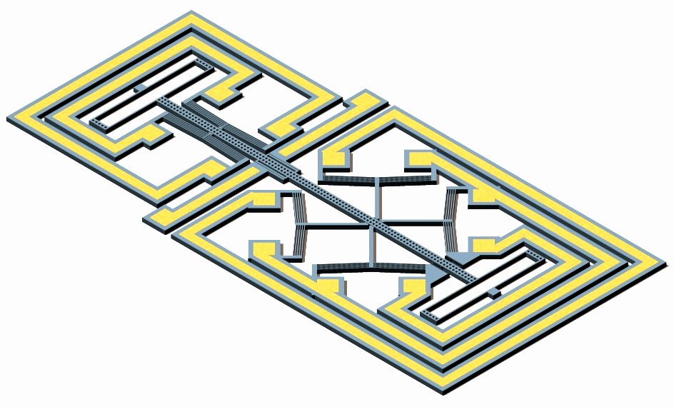
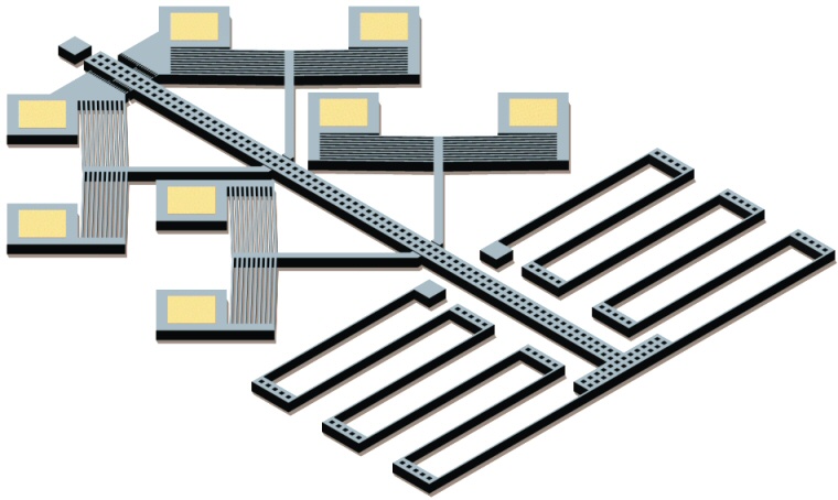
In the linear motor,
actuators are arranged in clamping and positioning arrays. The
motor works by advancing a slider through frictional contact. By
alternately positioning and clamping the slider, a very large
range of motion is available. The clamping ability allows the
motor to interact with compliant mechanisms and maintain a
specified position. This capability makes this type of motor
an excellent choice for integration with 3DMEMS
devices. 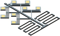
The efficiency of these thermal
motors is extremely low, approximately 0.0000001. This low
efficiency limits the use of microactuators in low-power
applications such as self-sufficient robotics. However, the
actuators are useful in stationary applications. For example, the nanotechnology company Zyvex uses thermal actuators in a nanomanipulation system.
Modeling
A key part of this work is the
estimate of the time constant of these thermal actuators.
Because the length of a typical
actuator beam is considerable larger than height or width, a 1-D
differential element is used to model the temperature
distribution in the silicon. This element, with height h,
width w, and thickness dx, is illustrated below,
where the current flux J represents the current per unit
area through the element.
In
this diagram, the current flux J represents the current
per unit area through the element. The material properties shown
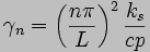
are the resistivity ρ, the silicon thermal
conductivity ks, and the air thermal
conductivity ka.
It has been shown that, in the
case of a very small gap under a suspended beam, the effects of
convection and radiation are negligible and conduction through
air to the substrate dominates. However, conduction from the
sides of the beam through the surrounding air to the substrate is
not negligible and must be accounted for by the shape conduction
factor S. This parameter is typically found via finite
element analysis.
Because of the relatively large
thickness of the substrate (525 µm),
the large 600 µm × 600 µm
anchors, and the high thermal conductivity of single-crystal silicon, the substrate
and anchor temperatures are assumed to remain at ambient
temperature. Finite element analysis of the complete geometry has
shown this assumption to be reasonable. The thermal conductivity
of air and the resistivity of silicon are assumed to be
independent of temperature. Also, the thermal conductivity and
thermal expansion coefficient of silicon are initially assumed to
be independent of temperature to make the heat equation
tractable.
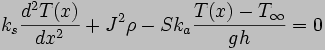
By using the differential
element above and dividing by the element volume, the
time-independent heat equation can be written as
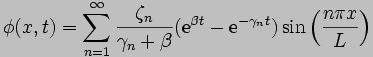
The transient response of the
V-beam thermal actuators can be predicted by examining the
time-dependent form of this equation:
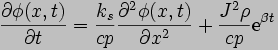

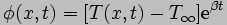
where the values of the specific
heat c and density p of silicon are assumed to be independent of
temperature, and the following variable substitutions have been
made:

Applying the finite Fourier
transform to the time-dependent equation results in the following
nonhomogeneous differential equation:
where
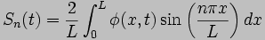
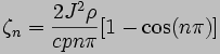
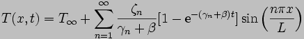
This equation has the solution

to which the inverse finite
Fourier transform can be applied:
The general solution is
therefore
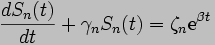
implying a first-mode time
constant of
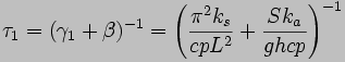
which offers a useful way of
comparing heat loss contributions from beam conduction and air
conduction. The first term represents heat loss through the beam
to the anchors; the second term represents heat loss through the
air gap to the substrate. By using typical values, a typical
V-beam actuator with a length L of 1000 µm,
a width w of 10 µm,
and a height h of 50 µm
is predicted to have a first-mode time constant τ1
of approximately 0.8 ms. The corresponding cut-off frequency is
approximately 200 Hz.
Transient experiments were
performed on the V-beam actuators with a laser Doppler
vibrometer. These tests were performed by mounting a chip
vertically and focusing the laser on the side of an actuator
beam. The normalized frequency response is shown below. As
expected, the full range of motion is maintained at low
frequencies. As the frequency increases past 100 Hz, response
drops 20 dB per decade because the actuator cannot complete each
heating/cooling cycle fast enough to keep up with the signal. By
fitting a curve to the frequency response, the time constant of
this actuator is estimated at 1.6 ms, as shown as the solid line
below.
It would seem that the transient
model is off by a factor of two. In fact, the earlier calculation
was performed with the room temperature values of silicon thermal
conductivity and specific heat. However, we know from resistance measurements and from visual observation of glowing silicon that portions of the actuators exceed 500°C during operation. What happens if high-temperature
values are used? If we take the material properties at
around 500°C, the calculated time constant is 1.8 ms. So the
experimental results are actually bounded by estimates using
temperatures of 25°C and 500°C. For better accuracy, we would need to model the beam by multiple elements, each with its own temperature and material properties.
Impact
This work was published here in 2004. Since then, our modeling and fabrication
work has been cited by over 100 papers investigating
electrothermal actuation and its applications and by the
books Modeling MEMS and NEMS by Pelesko and Bernstein (CRC
Press, 2002), RF MEMS: Theory, Design, and Technology by Rebeiz (Wiley 2003), Micromanufacturing and Nanotechnology by Mahalik (Springer, 2005) and MEMS Linear and Nonlinear Statics and Dynamics by Younis (Springer, 2011).
|