A model describing the combined electrical, thermal, and mechanical behavior of V-beam actuators has been developed. The model can be divided into three sections: electrothermal, thermomechanical, and transient analysis. In the electrothermal analysis, the temperature distribution along the actuator beams is found by solving the heat equation from an energy balance and boundary conditions. The thermomechanical analysis calculates thermal strain from the increase in beam temperature and employs the method of virtual work to predict deflection. Finally, an analysis of transient
behavior has been conducted to predict the maximum operational frequency of the actuators.
The parameters for this analysis are listed in Table
3. Due to the SOI wafer configuration, the height h of the beams represents the active layer thickness and the gap g between the beams and the substrate represents the oxide layer thickness.
Table 3.
Thermal actuation model parameters.
|
Parameter |
Value |
| c |
Specific
heat, silicon |
700
J/kg-K |
| E |
Elastic
modulus, silicon |
166
GPa |
| g |
Gap
between beams and substrate |
2
mm |
| h |
Height
of beams |
50
mm |
| ka |
Thermal
conductivity, air |
0.026
W/m-K |
| ks |
Thermal
conductivity, silicon |
148
W/m-K |
| p |
Density,
silicon |
2330
kg/m3 |
| T¥ |
Ambient
temperature |
298
K |
| a |
Thermal
expansion coefficient, silicon |
2.6
x 10-6 K-1 |
| r |
Resistivity,
silicon |
0.0133
W-cm |
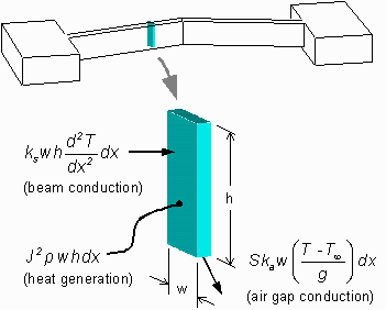
Because the length of a typical actuator beam is considerable larger than height or width, a 1-D differential element is used to model the temperature distribution in the
silicon. This element, with height h, width w, and thickness dx, is illustrated in
Figure 19, where the current flux J represents the current per unit area through the element.

Figure 19. Differential element of V-beam actuator used in electrothermal analysis.
It has been shown that, in the case of a very small gap under a suspended beam, the effects of convection and radiation are negligible and conduction through air to the substrate dominates
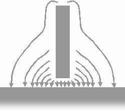
[42]. However, conduction from the sides of the beam through the surrounding air to the substrate is not negligible and must be accounted for by the shape conduction factor S. This geometric factor represents the ratio of heat loss from the sides and bottom of the beam to expected heat loss from the bottom of the beam only. An illustration of this method of heat loss is shown in
Figure 20.
Figure 20. Excessive heat loss from sides and top of suspended beam.
An empirical equation was developed by another group for 2 mm high polysilicon beams, but this equation does not scale up well for heights of 10 mm or more
[42]. Finite element simulations using ANSYS(tm) were performed to investigate the shape conduction factor associated with a beam height of 50 mm, corresponding to the active layer of the SOI wafers used in this research. The model used in the simulations
consisted of a beam cross section surrounded by air and separated by a small gap from an isothermal surface, representing the substrate. The temperature of this surface was set to the ambient temperature T¥ and a heat generation value of J2r was applied to the cross section of the beam. The simulation was run to convergence to provide the steady-state temperature in the cross section. These simulations confirmed the assumption that the temperature variation in the beam cross-section is negligible, supporting the use of the 1-D differential element in
Figure 19.
By equating the heat loss from conduction through the air gap and the heat gain from resistive heating, the shape conduction factor for a particular geometry can be found from the following equation:
(2)

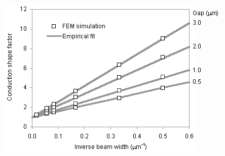
where T is the steady-state temperature throughout the beam cross section. In the simulations, the beam width was varied from 2 to 60 mm and the air gap was varied from 0.5 to 3 mm. The following equation was developed to fit the simulation data:
(3)

In Figure 21, predictions from the fitted equation are compared to the simulation results.

Figure 21. Comparison of conduction shape factor equation with simulation results. The beam height is 50 mm.
Because of the relatively large thickness of the substrate (525 mm), the large 600
x 600 mm anchors, and the high thermal conductivity of SCS, the substrate and anchor temperatures are assumed to remain at ambient temperature. Finite element analysis of the complete geometry has shown this assumption to be reasonable. The thermal conductivity of air and the resistivity of silicon are assumed to be independent of temperature. Also, the thermal conductivity and thermal expansion coefficient of silicon are initially assumed to be independent of temperature to make the heat equation tractable.
By using the differential element in Figure 19 and dividing by the element volume, the steady-state heat equation can be written as
(4)

or, by dividing by ks,
(5)

where the following variable substitutions have been made:
(6)

(7)

The solution to this second-order differential equation is
(8)

where L denotes the actuator beam length. This equation describes the temperature distribution in a silicon beam suspended in air and undergoing resistive heating from an applied current. The thermal expansion is calculated as
(9)

This value is not equivalent to actuator deflection, but represents the axial expansion of a uniform bar with the same temperature distribution. This expansion value is used in the thermomechanical analysis in the next section.


