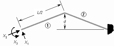
The V-beam actuator is statically indeterminate because both ends are clamped; however, the method of virtual work can be used to find the reaction forces and deflection [38,43]. In this section, the deflection and force at the midpoint of the actuator are calculated. By using the flexibility method of virtual work, the redundant constraints are released and replaced by two unit forces and one unit moment in the directions of X1, X2, and X3, as shown in Figure 22. Linear algebra can then be used to solve the following flexibility equation for X1, X2, and X3, which represent the actual constraint forces and moment at the released end:
Figure 22. Coordinate system and dimensions of V-beam actuator used in thermomechanical analysis.
In this equation, each flexibility coefficient fij represents the deflection of the released end in the direction of Xi due to a unit virtual force or moment in the direction of Xj, and is calculated by using the equation
where I and A are the moment of inertia and area of the beam cross section, and mki and nki are the bending moment and axial force in section k due to a unit value of the redundant constraint Xi [43]. Actuator sections are identified by the circled numbers in Figure 22. Additionally, the quantity fti is the deflection of the released end due to thermal strain in the direction of Xi if the redundant constraints are ignored, making the structure statically determinate. That is, the combined effects of the redundant constraints and the thermal strain must result in zero deflection and zero rotation of the released end, because it is actually fixed.
From Equation (11), the flexibility coefficients of the V-beam actuator are derived as
(12)

(13)

(14)

(15)

(16)
(17)

where d is the midpoint offset shown in Figure 22. Because the offset angle of the buckling actuator is typically less than 5 degrees, small-angle approximations are used. Thermal expansion produces the following deflections of the released end:
(18)


Once the redundant reaction forces have been found, the actuator deflection is found through linear beam theory [43]. From Castigliano’s theorem, the deflection at the midpoint due to thermal strain can be derived as
where X1 and X3 are found by solving Equation (10). This deflection can be approximated to within 1% by the following equation:
The force exerted by the actuators can be predicted by calculating the deflection resulting from a unit force and comparing it to the deflection caused by Joule heating [44]. In other words, if a dummy force P applied at the midpoint of the actuator results in a deflection of magnitude up, the free deflection ut from thermal strain should correspond to the maximum force Ft, where
(21)

for any value of P, because the thermomechanical model employs linear beam theory. More generally, if a unit force is assumed for P, the force F exerted by a V-beam actuator at any deflection u is
(22)

which is linear in u. As expected, this equation predicts the maximum force when the actuator is held in place (u = 0) and zero force at maximum deflection (u = ut). The deflection up is calculated from Equations (10) and (19) and where fti is replaced by fpi:
(23)


These coefficients were calculated from Equation (11) where mkp and nkp are the bending moment and the axial force in section k due to a unit value of the force P.
The maximum force can also be approximated within 1% by the following equation:
These approximations are used in the design strategy section to determine the effects of changes in geometry on actuator performance.


