In this section, a design strategy for V-beam thermal actuators is presented. By using the model described above, actuator dimensions can be optimized according to design requirements. Actuator performance can be compared to the benchmark of axial thermal expansion of a bar, which may be thought of as the degenerate case of a V-beam actuator with coincident anchors. This bar exerts a relatively large amount of force compared to V-beam actuators; however, deflections are typically too small to be useful. For example, a silicon bar of comparable dimensions to the V-beam actuators is expected to exert a maximum force Ft of over 75 mN for an average temperature increase of 350 K. However, the expected free deflection ut is less than 1 mm. The V-beam actuators described in this work employ the characteristics of a clamped-clamped beam and a fabricated midpoint offset to increase deflection at the expense of exerted force.
Actuator deflection and force are proportional to thermal expansion. Some general options for increasing expansion are increasing the gap g, running the actuators in a vacuum, or running the actuators at elevated temperatures to take advantage of temperature-dependent properties. These options will all result in larger deflections for a given power input.
By using Equations (20) and (24), the deflection and force per unit power can be derived as
(43)

(44)

where C represents a factor of excessive deflection due to the advantageous temperature-dependent properties of silicon. This factor is a function of thermal conductivity, the coefficient of thermal expansion, and the temperature distribution throughout the actuator.
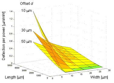
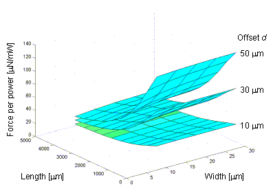
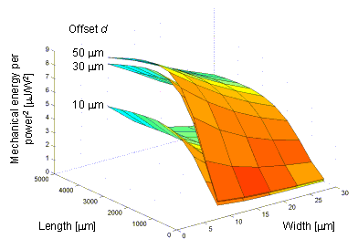
The effects of changing actuator dimensions on deflection per unit power and force per unit power are illustrated in Figure 33 and Figure 34. The excess deflection factor C is taken to equal 3 (for the dimensions modeled, C varies between 1.7 and 4.0). Figure 35 shows the product of deflection per unit power and force per unit power as a measure of general actuator efficiency.
Figure 33. Predicted actuator deflection per unit power.
Figure 34. Predicted actuator force per unit power.
Figure 35. Product of deflection per unit power and force per unit power.
Based on these three charts, it can be seen that the width should be made as small as design rules allow to increase deflection without reducing force. A trade-off exists between deflection and force depending on the offset size, which can be set to favor one or the other. Applications can usually be classified as either low-force or high-force. For low-force, high displacement applications such as component positioning, frequently the only opposing force is sliding friction. In these situations, small offset values work best by maximizing deflection. For high-force applications such as positioning 3DMEMS compliant joints, larger offset values are recommended. The minimum practical offset value equals the beam width; smaller offsets may not be reliably resolved during fabrication. Additionally, at very small offset values, buckling effects dominate and actuation may be erratic.
Parallel arrays of actuators such as the one shown in Figure 18 provide increased total force but not increased deflection; the maximum available deflection depends on the actuator geometry and the maximum operational current. Increasing actuator length up to the limit of available space is the best way to increase deflection per unit power. It should be noted that the maximum deflection ut and the maximum force Ft are not available simultaneously because of the nature of the actuator geometry. Therefore, if an application requires a deflection u and a force F simultaneously, the necessary V-beam design must satisfy
where n is the number of actuators.
The preceding design strategy can be applied to the problem of positioning 3DMEMS devices. One possible positioning method is an electrothermal motor that uses translational steps from actuator arrays to push a slider through an unlimited range. Assuming that each step requires 10 mN force at a deflection of 10 mm, the actuator arrays can be optimized for minimum space and power. It has been shown that these actuators are most efficient when the width is minimized and the maximum temperature in the beams is 800 K. Assuming a length L of 1000 mm, a fabricated width w' of 8 mm, and a height h of 50 mm, the maximum operational current is calculated by the numerical solution to be 24 mA. At this current, the predicted free deflection ut is 20.9 mm and the predicted maximum force Ft is 2.8 mN at an offset of 8 mm. In general, the free deflection should be 1.5 to 2 times the necessary displacement because available force is proportional to the difference between u and ut. With these deflection and force values, the number of required actuators is calculated by using Equation (45) to be seven; the total power required is 1.34 W.
Table 5 lists the performance data for actuators of different lengths at the maximum current. The number of actuators and power required for a 10 mm / 10 mN application is also given. In all cases, the largest possible offset was used to maximize force while keeping displacement around 20 mm. It can be seen that increasing actuator length can greatly reduce power requirements, though at the expense of increasing motor size.
Table 5. Actuator array requirements for 10 mm / 10 mN output.
Length (mm)
ut (mm)
Ft (mN)
Offset (mm)Actuators
requiredTotal
power (W)1000
20.9
2.8
8
7
1.34
1500
22.7
7.7
32
3
0.66
2000
17.9
15
120
2
0.53
3000
23.9
23
160
1
0.40
A final design consideration is whether failure by buckling is possible during normal V-beam actuator operation. If the midpoint of an actuator is fixed, the maximum possible exerted force is limited by the critical buckling load, calculated as
(46)

for each beam half, where L is the total actuator length [49]. The compressive axial load in the beam consists of the force X2, which can be approximated as
(47)

By using the approximation for exerted force Ft approximated in Equation (24), the critical exerted force is calculated as
(48)

For the first actuator configuration listed in Table 5, this critical force is calculated to be 3.6 mN, which is greater than the 2.8 mN force available at the maximum operational current. The margin of safety is even larger for the other actuator configurations in Table 5. Consequently, failure by buckling is not expected to occur for these configurations during normal operation.


